LINE SECTIONALIZING USING A PLC AND ABB PROTECTIVE RELAY
Page 3 of 53
3.
The PLC immediately opens the breaker at Feeder Location 3. The PLC verifies that reading
the status of the breaker opens the breaker. The MAGELIS system immediately displays the
metering values and breaker status on its screen and may also generate alarms to alert the
operator or attached SCADA system.
4.
If Substation Location 2 has sufficient reserve to supply the feeder at location 3, the PLC wait
3 seconds to ensure that the TPU at Substation Location 1’s breaker is open, AND that the
Breaker at Substation Location is also open.
5.
The PLC shall Close the breaker at Substation Location 2 and read the metering values and
breaker status reported by the DPU2000R.
6.
The PLC still calculates the load on the line and determines if there is still sufficient reserve to
add additional feeder lines, the PLC shall wait another 1 second and send a close command
to the breaker controlled by the PCD2000.
7.
The PLC shall read the metering values and breaker statuses at each of the 3 IED locations
and report them to the MAGELIS system via the internal network at the substation.
8.
At each of the above steps, a message is generated as to the step being performed by the
PLC. The status of each step (along with any error) messages is displayed and archived by
MAGELIS operator interface. The PLC will place the restoration scheme in MANUAL mode,
so that an operator may place the system in the same state that it was in prior to the
TPU2000R trip.
If any one of the steps fails to execute, the MAGELIS HMI will display an error message as to the cause
of failure in the restoration process.
MANUAL MODE disables the PLC’s capability to trip/close the breaker. The PLC still computes the
loading values and alerts the operator as to alarms. The PLC also communicates with MAGELIS MMI
and displays messages/ breaker status information/metering data informing the operator if adequate load
is available to supply the feeder. This gives the operator additional information if a manual restoration is
to be performed via the operator interface. Additionally, the operator commands may be sent directly to
the PLC to perform manual trips and close commands.
Method of Implementation
Two Ladder Logic instructions within the Modicon PLC allows line sectionalizing to occur:
•
MSTR obtains the data from the TPU relay. Once the data is obtained, the PLC
determines the field conditions and decides upon the control to be performed.
•
XMIT instructions when executed by the PLC, initializes the COM port resident on the
unit. The PLC can then act as an Remote Terminal Unit (RTU). The PLC then
interrogates the DPU2000R and PCD2000 to determine if the units are available to
be switched.
The remainder of this application note explains the programming process and ladder logic required to
implement the application pictured in Figure 1.
Obtaining Relay Information Via Modbus Plus and Modbus
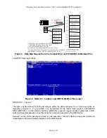
The PLC is programmed using four ladder logic segments. The logic within each segment is as follows
(for this example).
SEGMENT 1: READ TPU2000R VALUES VIA MODBUS PLUS. PROVIDE MANUAL TPU
CONTROL OPERATIONS VIA MODBUS PLUS.
SEGMENT 2: READ DPU2000R AND PCD2000 VALUES VIA THE RADIO MODEMS USING MODBUS
PROTOCOL. PROVIDE MANUAL AND AUTOMATED CONTROL OPERATIONS VIA MODBUS.
Summary of Contents for REL 356
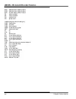
Page 23: ...ABB REL 356 Current Differential Protection 1 10 Product Overview and Specifications ...
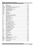
Page 83: ...ABB REL 356 Current Differential Protection 3 36 Settings and Application ...
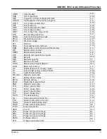
Page 127: ...ABB REL 356 Current Differential Protection 5 28 Testing ...
Page 186: ...LINE SECTIONALIZING USING A PLC AND ABB PROTECTIVE RELAY Page 49 of 53 ...
Page 187: ...LINE SECTIONALIZING USING A PLC AND ABB PROTECTIVE RELAY Page 50 of 53 ...
Page 188: ...LINE SECTIONALIZING USING A PLC AND ABB PROTECTIVE RELAY Page 51 of 53 ...
Page 189: ...LINE SECTIONALIZING USING A PLC AND ABB PROTECTIVE RELAY Page 52 of 53 ...


