29
8.3 Modulating pump modes
There are several modulating pump modes implemented in the software. By selecting a different modulating pump
mode, the pump behaviour can be changed. The following modulating pump modes are available.
Modulating pump mode
Details
0:
Disabled
No pump modulation; the PWM duty cycle is always 0%.
1:
Delta temperature modulation
Calculated duty cycle to create a delta temperature between the T_Supply and
T_Return sensor.
2:
Fixed 20% speed
Fixed duty cycle of 20%.
3:
Fixed 30% speed
Fixed duty cycle of 30%.
4:
Fixed 40% speed
Fixed duty cycle of 40%.
5:
Fixed 50% speed
Fixed duty cycle of 50%.
6:
Fixed 60% speed
Fixed duty cycle of 60%.
7:
Fixed 70% speed
Fixed duty cycle of 70%.
8:
Fixed 80% speed
Fixed duty cycle of 80%.
9:
Fixed 90% speed
Fixed duty cycle of 90%.
10: Fixed 100% speed
Fixed duty cycle of 100%.
8.3.1 D
ELTA TEMPERATURE MODULATION
When the modulating pump mode 1 Delta temperature modulation is selected the pump modulates to create a delta
of T_Delta between the T_Supply and T_Return sensors. This modulation is only done when the control is in burn.
When the burner starts the duty cycle is kept at the Default Duty cycle setting for the time set by Burn Stabilize
Time. After this time, the PID calculated duty cycle is used.
During modulation, the duty cycle output changed according to the following logic:
• Actual delta temperature is greater than the selected T_Delta
• The pump speed increases so there is less time to cool down the heated water. This results in the T_Return
temperature increasing.
• Actual delta temperature is smaller than the selected T_Delta
• The pump speed decreases so there is more time to cool down the heated water. This results in the T_Return
temperature decreasing.
8.4 Pump: maximum electrical power
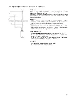
General
- The inrush current of a conventional pump is approximately 2½ x its nominal current.
- The maximum allowed switch current of the PCB is 4 A.
- The total current of PCB and gas valve is approx. 0.5 A, so the total current of additional pumps and valves
may not exceed 3.5 A. Use separate relays if higher currents are needed.
Pump P1 - boiler pump.
This pump is NOT part of the appliance. The maximum nominal current for it is 1.5 A, so its maximum electrical
power is 230 VAC x 2 A = 460 W.
Pump P2 - calorifier pump.
Pump P2 is a DHW pump, meaning it’s not part of the appliance, is also used for heating of an indirect calorifier.
The maximum nominal current of pump P2 must also be < 2 A.
3-way valve.
The combined nominal current of pump P1 and the 3-way valve must be smaller than 2 A.
Pump P3 - system pump.
The nominal current of pump P3 and the other connected pumps must be equal to or lower than 2 A.
Warning (EC pumps):
In case of using an electronic commutating pump with a higher inrush current than 8 A, the boiler control may not
be used for the power connection, because of the inrush current of the electronics of the pump. Directly connect
the pump to an external power supply
.
WARNING: Use an external relay if pump current exceeds 2 A .
Summary of Contents for S-CBX 105
Page 2: ......
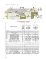
Page 40: ...40 9 10 Flue Terminal Positioning ...
Page 42: ...42 9 11 1 FIGURE 12 LINE G ...
Page 55: ...55 11 5 Ladder Logic Diagram ...
Page 56: ...56 11 6 Electrical schematics ...
Page 57: ...57 ...
Page 137: ......

