background image

Cryo-con Model 24C

Front Panel Menu Operation

Sensor Setup Menu

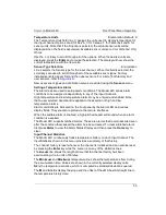
The Sensor Setup menu is used to view and edit user temperature sensor data.

The Sensor Header Edit Menu

Pressing the 

Sensor

 key from the Home Status Display accesses the Sensor Setup 

Menu. From there, the Sensor Header Edit Menu can be accessed by by scrolling to 
the sensor and pressing 

Enter

.

Definition of a sensor requires entering configuration data on this screen followed by 
entering a calibration curve.

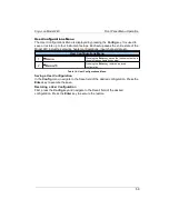
Sensor Header Edit Menu

+

Sets the Sensor Type. 

#

Sets the sensor Temperature Coefficient and Calibration 
Curve Multiplier.

+

Sets Units of the sensor’s Calibration Curve. Choices 
are: Ohms, Volts and LogOhm.

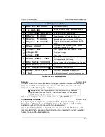
Table 24: Sensor Setup Menu

The first line on this menu is the sensor table index. Selecting this field allows the 
user to scroll through all of the sensors configured in the unit, including user sensors. 
The index is displayed along with the sensor name.
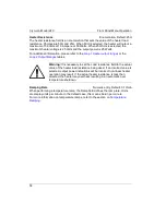
Note: the sensor name may be entered via any of the Remote I/O interfaces, but may 
not be changed from the front panel.
Sensor Type is an enumeration of all of the basic sensor types supported by the 
Model 24C. Choices are shown in the 

Supported Sensor Configurations

 table above.

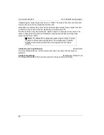
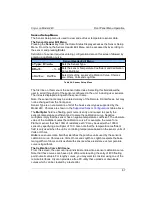
The 

Multiplier

 field is a floating-point numeric entry and is used to specify the 

sensor's temperature coefficient and to scale the calibration curve. Negative 
multipliers imply that the sensor has a negative temperature coefficient. The absolute 
value of the multiplier scales the calibration curve. For example, the curve for a 
Platinum sensor that has 100

 of resistance at 0

C may be used with a 1000


sensor by specifying a multiplier of 10.0. Also note that the temperature coefficient 
field is only used when the unit is controlling temperature based on the sensor units of
Volts or Ohms.

Units

 is an enumeration field that identifies the primitive units used by the sensor’s 

calibration curve. Choices are Volts, Ohms and LogOhm. LogOhm selects the base 
ten logarithm of ohms and is useful with sensors whose resistance vs. temperature 
curve is logarithmic.

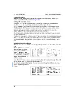
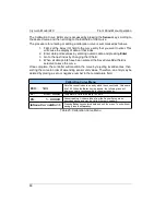
The Calibration Curve Edit menu

From this screen, the user can input individual entries into a sensor calibration curve. 
Note that these curves can have up to 200 points requiring the entry of 400 floating 
point numeric values. For lengthy curves, you may want to consider using one of the 
remote interfaces. Cryocon provides a free PC utility that  uploads or downloads 
curves which can be created by a text editor.

67

Summary of Contents for 24C

Page 1: ...User s Guide Model 24C Cryogenic Temperature Controller CRYOGENIC CONTROL SYSTEMS INC P O Box 7012 Rancho Santa Fe CA 92067 Tel 858 756 3900 Fax 858 759 3515 www cryocon com ...

Page 2: ... specifications for the product or improper site preparation or maintenance The design and implementation of any circuit on this product is the sole responsibility of the Buyer Cryo con does not warrant the Buyer s circuitry or malfunctions of this product that result from the Buyer s circuitry In addition Cryo con does not warrant any damage that occurs as a result of the Buyer s circuit or any d...

Page 3: ... Form Factors and Environmental 38 Front Panel Operation 41 The Keypad 41 The Front Panel Display 46 Front Panel Menu Operation 51 Instrument Setup Menus 51 Basic Setup and Operation 73 Configuring a Sensor 73 Using NTC Sensors 74 Using PTC resistor sensors 76 Downloading a Sensor Calibration Curve 77 Autotuning 80 Temperature Ramping 85 Cryocooler Signature Subtraction 88 Using an external power ...

Page 4: ...rol Loops 157 Introduction 157 Various methods for obtaining PID coefficients 157 Manual Tuning Procedures 158 Appendix E Sensor Data 159 Cryo con S700 Silicon Diode 159 Cryo con S900 Silicon Diode 160 Cryo con R500 Ruthenium Oxide Sensor 161 Cryo con R400 Ruthenium Oxide Sensor 162 Sensor Packages 163 Appendix F Configuration Scripts 167 Script File Structure 167 Script File Example 170 Appendix ...

Page 5: ...nt Kit 10 Figure 3 Model 24C Rear Panel Layout 37 Figure 4 Model 24C Front Panel Layout 41 Figure 5 Thermocouple Module 95 Figure 6 Thermocouple Switches 95 Figure 7 Proper Assembly of the Input Connector 181 Figure 8 Diode and Resistor Sensor Connections 182 Figure 9 RS 232 Null Modem Cable 184 v ...

Page 6: ...ontrol Loop Setup Menus 55 Table 19 User Configurations Menu 59 Table 20 System Configuration Menu 60 Table 21 Over Temperature Disconnect Configuration 62 Table 22 Network Configuration Menu 64 Table 23 PID Table Edit Menu 66 Table 24 Sensor Setup Menu 67 Table 25 Calibration Curve Menu 68 Table 26 Auto Tune Menu 69 Table 27 digital output Status Indicators 71 Table 28 Digital Output Modes 71 Tab...

Page 7: ...perature Examples include Ruthenium oxide Carbon Glass Cernox Carbon Ceramic Germanium and several others Their resistance and sensitivity increase dramatically at low temperature but their sensitivity is usually poor at warmer temperatures The Model 24C provides robust support for NTC resistor sensors by using constant voltage AC excitation In the warm region where the sensor has low resistance a...

Page 8: ... scale ranges are available in decade increments down to 500mW full scale 2 Loop 2 is a linear heater with two output ranges of 25 Watts and 2 5 Watt full scale into a 50 load 3 Loop 3 and 4 are a non powered analog voltage output intended to control an external booster power supply Output is selectable at 10 or 5 Volts full scale User Interface The Model 24C s user interface consists of a large b...

Page 9: ... accuracy temperature measurements without expensive sensor calibrations Data logging is performed by continuously recording to an internal 1 365 entry circular buffer Data is time stamped so that the actual time of an event can be determined Non volatile memory is used so that data will survive a power failure Input Channel Statistics The Model 24C continuously tracks temperature history independ...

Page 10: ...4C connects directly to any Ethernet Local Area Network LAN to make measurements easily and economically TCP IP and UDP data port servers brings fast Ethernet connectivity to all common data acquisition software programs including LabView An ASCII text based command language identical to those commonly used with GPIB or RS 232 interfaces is implemented This is the primary way that user software in...

Page 11: ...Cryo con Model 24C Introduction 5 ...

Page 12: ...ly configure an instrument including setting custom sensor calibration curves and PID tables Further scripts can query and test data They are commonly used in a manufacturing environment to set a baseline state and test a target product In the laboratory scripts can be used to save and restore configurations for various experiments XML Extensible Markup Language is used for the structure and forma...

Page 13: ...ut connector kit 4124 018 consisting of a 10 pin detachable terminal block 04 0007 and a dual banana plug 04 0433 Detachable 120VAC USA Line Cord 04 0310 or universal Euro cord Certificate of Calibration Verify the AC Power Line Voltage Selection The AC power line voltage is set to the proper value for your country when the controller is shipped from the factory Change the voltage setting if it is...

Page 14: ...essage display In this case turn the unit off and refer to Appendix C Troubleshooting Guide Caution Do not remove the instrument s cover or attempt to repair the controller There are no user serviceable parts jumpers or switches inside the unit Further there are no software ROM chips trim pots batteries or battery backed memories All firmware installation and instrument calibration functions are p...

Page 15: ... on the rear panel It is important to allow at least of clearance on the left and right sides and to ensure that the exhaust path of the fan is not blocked Rack Mounting You can rack mount the controller in a standard 19 inch rack cabinet using the optional rack mount kit Instructions and mounting hardware are included with the kit 4122 030 Single instrument 2U rack mount kit 4034 032 Single instr...

Page 16: ...mount kits extends the height of the controller from 2U 3 to 3U 5 Since the controller is an industry standard size it is possible to mount any similar size instrument next to it in the rack Warning When using the shelf type rack mount kits do not use screws that protrude into the bottom of instrument more than Otherwise they can touch internal circuitry and damage it 10 Figure 2 4034 032 Rack Mou...

Page 17: ...ere the maximum output power will not damage the equipment To set this parameter press the Loop 1 key and refer to the Loop Configuration Menu section 3 The controller has an over temperature disconnect feature that monitors a selected input and will disconnect both control loops if the specified temperature is exceeded This feature should be enabled in order to protect your equipment from being o...

Page 18: ... terminal block plug detachable power cord and a certificate of calibration Specify AC Line Voltage when ordering 100 Configured for 90 100VAC with detachable USA power cord 110 Configured for 110 120VAC with detachable USA power cord 220 Configured for 220VAC with detachable universal Euro Shuko line cord 240 Configured for 240VAC with detachable universal Euro Shuko line cord Options Description...

Page 19: ...Level As of July 2014 the hardware revision level for the Model 24C series is C Returning Equipment If an instrument must be returned to Cryo con for repair or recalibration a Return Material Authorization RMA number must first be obtained from the factory This may be done by Telephone FAX or e mail When requesting an RMA please provide the following information 1 Instrument model and serial numbe...

Page 20: ...E 488 2 Interface Bus Cable 6 6 04 0310 AC Power Cord 04 0317 AC Power Cord Cont European Shuko 04 0414 Din 6 Sensor Input Connector Amphenol T3400 001 04 0007 Ten pin detachable terminal block for Loop 2 and relay connections 04 0433 Dual banana plug for Loop 1 connection 4042 040 8 Sensor cable four wire wired to DIN 6 connector 3124 029 Additional User s Manual CD Table 1 Model 24C Instrument A...

Page 21: ...ture sensor Temperature range 100mK to 40K CP 100 CP 100 series Ceramic Wound RTD 100 GP 100 GP 100 series Glass Wound RTD 100 XP 100 XP 100 series Thin Film Platinum RTD 100 XP 1K XP 1K series Thin Film Platinum RTD 1 000 3039 002 Cartridge Heater Silicon free 25 25 Watt 1 4 x 1 1 8 Temperature range to 1 600K 3039 001 Cartridge Heater Silicon free 50 50 Watt 1 4 x 1 1 8 Temperature range to 1 60...

Page 22: ......

Page 23: ...t channel key ChA ChB ChC or ChD to select the desired channel for configuration The first line of the Input Channel Configuration menu is used to change the sensor units It shows the selected input channel the current temperature in real time and the current units An example is shown here To change the sensor units use the and 0 keys to scroll through the available options When the desired units ...

Page 24: ...d An example is shown here Use the and 0 keys to select between a 50 Ohm and a 25 Ohm heater and then press the Enter key Use the navigation keys to scroll to the Range field and then select the desired heater range Be sure to select a range that does not exceed the ratings of your cryostat A summary of full scale output power for the various ranges is given here Range Max Output Power 25 50 Hi 25...

Page 25: ...bled the controller will automatically begin controlling temperature whenever AC power is applied For a complete description of this function please see the Auto Ctl function in the System Functions menu section Restoring Factory Defaults Factory default settings may be restored with the following simple procedure 1 Turn AC power OFF by pressing the Power key 2 Press and hold the Enter key while t...

Page 26: ......

Page 27: ...e Sensor Connections section Supported Sensors Include Type Excitation Temperature Range Example Silicon diode 10mA DC 1 4 to 475K Cryo con S900 SI 440 430 410 Lakeshore DT 670 470 Platinum RTD Constant Current 1mA AC 14 to 1200K Cryo con CP 100 Cryo con GP 100 Cryo con XP 100 Cryo con XP 1K Cernox Constant Voltage AC 100mK to 420K Lakeshore all types Ruthenium Oxide Constant Voltage AC 100mK to 2...

Page 28: ...t mode 10mA 0 05 DC excitation Note Current source error has negligible effect on measurement accuracy Input voltage range 0 to 2 00VDC Accuracy 80mV 0 005 reading Resolution 2 3mV Drift 25ppm ºC over an ambient temperature range of 25ºC 5ºC PTC Resistor Sensors Configuration Constant Current AC resistance bridge mode Ratiometric measurement cancels any error in excitation current Drift 20ppm ºC o...

Page 29: ...nstant Voltage AC resistance bridge with excitations of 10mV 3 0mV 1 0mV and 300µV RMS Fixed or auto ranged Excitation Current 2 5mA to 10nA Four ranges of 2 5mA 250uA and 25uA full scale Excitation Frequency 7 5Hz bipolar square wave Drift 10W and 10KW 15ppm ºC 10W or 10KW 25ppm ºC over an ambient temperature range of 25ºC 5ºC DC Offset Current 8nA by active cancellation Resistance Range 0 5W to ...

Page 30: ... the maximum to the minimum resistance shown below Resistance Range Excitation Current Range Min Max Resistance Accuracy at 25C 1Ω 1 0mA 1 4Ω 0 02Ω 0 05 Rdg 4Ω 1 0mA 4 40Ω 0 02Ω 0 05 Rdg 40Ω 100µA 40 400Ω 0 2Ω 0 05 Rdg 400Ω 10µA 400 4KΩ 2 0Ω 0 05 Rdg 4KΩ 10µA 4K 40KΩ 20Ω 0 05 Rdg 100KΩ 10µA 40K 100KΩ 50Ω 0 1 Rdg Table 9 10mV Constant Voltage Accuracy Specifications While it is possible to measure ...

Page 31: ...V or 50V Ranges Three output ranges of 1 0A 0 33A and 0 10A full scale which correspond to 50W 5 0W and 0 5W when used with a 50 load Load Resistance 25 or 50 for maximum output Minimum Load 10 in 25 setting 40 in 50 setting Digital Resolution 1 0PPM of full scale corresponding to 20 bits Readback Heater output power Heatsink temperature Connector Dual Banana plug Loop 2 Heater Output Type Short c...

Page 32: ...00 Baud IEEE 488 GPIB External option Full IEEE 488 2 compliant USB 2 0 External option Serial port emulator Language Remote interface language is IEEE 488 2 SCPI compliant Further it is identical within the entire Cryo con instrument line Compatibility National Instruments LabView drivers available for all interfaces Ethernet API available for C and Basic User Setups Four User Setups are availabl...

Page 33: ...r reading in Volts at the desired temperature SenSen is the sensor sensitivity in Volts Kelvin at the desired temperature For example to calculate the measurement accuracy of the Model 24C using a Cryo con S900 sensor at 10K look up the sensor reading and sensitivity in the S900 data table in Appendix G At 10K SenRdg is 1 36317 Volts and SenSen is 0 002604 Volts Kelvin Therefore and The result is ...

Page 34: ...ues show that MAR 0 004038W and MAT 9 5mK For ranges other than PTC100 please refer to the PTC Specifications table NTC Resistor Sensors The formulas for NTC resistor sensors are Where MAR is the electronic Measurement Accuracy in Ohms Range is the resistance range in Ohms 100 1K or 10K MAT is the Measurement Accuracy in Kelvin SenVal is the sensor reading in Ohms at the desired temperature SenSen...

Page 35: ...er the only use for measurement resolution is to compute control stability Since control stability is limited by the output DAC rather than the input the measurement resolution specification is limited to one part in 2 20 Where MR is the electronic measurement resolution in sensor units FullScale is the full scale range MRT is the measurement resolution in temperature units SenSen is the sensor se...

Page 36: ...Channel Table 10 Supported Sensor Configurations Bias types are CI Bridge maintains a constant current through the sensor CV Bridge maintains a constant voltage drop across the sensor i Note Any disconnected inputs to the Model 24C should be set to type None This will turn the input off Silicon Diode Sensors Silicon diode sensors 2 volt diodes are configured with a 10mA current source excitation a...

Page 37: ...atinum sensors These curves have been extended down to 14K Below that the sensors can be used with user supplied calibration curves A table of recommended setups for various types of PTC resistor sensors is shown here Type Measurement Range Sensor Excitation Platinum 100 1 0K 0 01 1 0mA AC Platinum 1000 10K 0 1 100mA AC Rhodium Iron 1 0K 0 01 1 0mA AC Table 11 PTC Resistor Sensor Configuration Whe...

Page 38: ... sensors please refer to the section titled Voltage Bias Selection Power dissipation in the sensor is computed by sensor bias d R V P 2 The actual power being dissipated in the sensor may be viewed in real time by going to the Input Configuration Menu An asterisk character next to the temperature display indicates that the resistance bridge is not balanced at the proper voltage bias When used with...

Page 39: ...stics Input temperature statistics are continuously maintained on each input channel This data may be viewed in real time on the Input Channel menu or accessed via any of the remote I O ports Statistics are Minimum Temperature Maximum Temperature Temperature Variance Slope and Offset of the best fit straight line to temperature history Accumulation Time The temperature history may be cleared using...

Page 40: ...0V 0 333A 2 5 Watts 5 0 Watts Low 25V 50V 0 100A 0 25 Watts 0 50 Watts Table 12 Loop 1 Heater output ranges Take care to ensure that the proper load resistance is selected Connection to a 25 load while a 50 is selected will result in overheating and eventual automatic heater shutdown Conversely connection to a 50 load while setting a 25 load will result in the dissipation of only one half of the i...

Page 41: ...d overshoot and time to stability at the new setpoint can be delayed for an extremely long time This is especially true in cryogenic environments where process time constants can be very long 3 Dithering and filtering the outputs in order to increase output resolution and improve control stability The PID Table control mode is a PID control loop just as described above However it is used to look u...

Page 42: ... or a remote interface Furthermore relays can be manually asserted ON or OFF Normally Open contacts are available on the rear panel Contact rating is 10A 125 VAC 5A 250 VAC or 5A 30 VDC for resistive loads Maximum switching power is 150W Remote Interfaces Ethernet LAN and RS 232 interfaces are standard IEEE 488 2 GPIB and USB are external field installable options All functions and read outs avail...

Page 43: ...safety standards User replaceable fuses are incorporated in the Power Entry Module i Note The Model 24C uses a smart power on off scheme When the power button on the front panel is pressed to turn the unit off the instrument s setup is copied to flash memory and restored on the next power up If the front panel button is not used to toggle power to the instrument the user should configure it and cy...

Page 44: ...s that may be removed by pulling out the fuse modules below the voltage selector Fuses are specified according to the AC power line voltage used Mechanical Form Factors and Environmental Enclosure The Model 24C enclosure is standard 2 U half width 17 inch rack mountable type that may be used either stand alone or incorporated in an instrument rack Dimensions are 8 5 W x 3 5 H x 12 D Weight is 9 Lb...

Page 45: ...s There are no internal user serviceable parts or adjustments Refer instrument service to qualified maintenance personnel Do not replace components with power cable connected To avoid injuries always disconnect power and discharge circuits before touching them Cleaning Do not submerge instrument Clean exterior only with a damp cloth and mild detergent Grounding To minimize shock hazard the instrum...

Page 46: ......

Page 47: ...e same function regardless of the context of the display The Power key is used to turn AC power to the controller on or off Note that this key must be pressed and held for one second in order to toggle AC power i Note The Model 24C uses a smart power on off scheme When the power button on the front panel is pressed to turn the unit off the instrument s configuration is copied to flash memory and r...

Page 48: ...figuration menus the keypad is used for navigation and data entry When the display is in the Home Status Display their function is identified by a label printed just above the key and is as follows ChA ChB ChC ChD Go to the Input Channel Setup menu Loop 1 Loop 2 Go to the Control Loop Setup menu Auto Tune Go to the auto tuning menu for either loop Config Go to the User Configurations menu Sensors ...

Page 49: ...over the symbol To select the displayed value press the Enter key To cancel selection without updating the field press the Esc key To select the displayed value press the Enter key To cancel selection without updating the field press the Esc key The cursor will then return to the symbol Numeric Data Fields Numeric data is indicated by a pound sign in the first column of the field The Keypad Keys a...

Page 50: ...its previous value The key can be used as a backspace i Note Up to 20 digits may be entered in a numeric field When digit entry has exceeded the display field width additional characters will cause the display to scroll from right to left When entry is complete the updated display field may not show all of the digits entered because of limited field width however the digits are retained to the ful...

Page 51: ...nput Channel Menu for Channel C 3 ChD Input Channel Menu for Channel D 4 Options Options Setup Menu Loop 3 and 4 setup menus 5 Loop 1 Go to the Loop 1 setup menu 6 Loop 2 Go to the Loop 2 setup menu 7 Sensors Sensor data and calibration curve menu 8 PID Table PID table menu 9 Auto Tune Autotune menu Table 15 Keypad key functions The LED indicators and Audible Alarm There are three LED indicators l...

Page 52: ...e sensor type and excitation level Loop Status Displays These displays show the current status of a selected control loop The control loop s input temperature is shown in 2x font Above is the loop and channel indicator the input channel s name string and alarm status Below in 1x font is the loop s setpoint heater range and percent of full scale output power Input Channel Statistics Display The Cha...

Page 53: ...a blank display is shown Temperature units are selected in the individual input channel setup menus ChA ChB ChC or ChD Temperature Units may be K C or F When Sensor Units S is selected the raw input readings are exhibited These will be in Volts or Ohms Sensor Fault Display A sensor fault condition is identified by a temperature display of seven dash characters as shown here The sensor is open disc...

Page 54: ...heater This fault is usually the result of a shorted heater or use of a heater with significantly less resistance than the selected load resistance After the controller has been allowed to cool to an acceptable temperature pressing the CONTROL button will clear the error and restore control mode 3 OTDisconn indicates that the heater output was disconnected by the Over Temperature Disconnect Monito...

Page 55: ... can be read to an accuracy of 2 Note that the bar chart does not have a loop number indicator Some examples are Loop ON zero output Loop OFF Loop ON 50 output i Note The Model 24C uses an independent circuit to read current actually flowing through the load The heater bar graph shows this measured current If the unit is controlling temperature but the bar graph indicates zero current flow an erro...

Page 56: ......

Page 57: ...menu is accessed by pressing the Set Pt key This gives one key access to the setpoints for all of the control loops Press the Home key to exit the menu without update The Alarm Status Display Menu The current status of the temperature alarms may be viewed by pressing the Alarm key Alarms are set for each input channel using the Input Channel Setup menu described below When an alarm is asserted the...

Page 58: ...at the current sensor is number 20 3 Input Config Go to the input configuration menu 4 CalGen Go to the CalGen screen 5 Statistics Go to the input channel statistics screen 6 Setpoint for the High Temperature alarm Use the keypad for numeric entry and then press the Enter key 7 High temperature alarm enable Selections are Yes or No 8 Setpoint for the Low Temperature alarm 9 Enables latching alarms...

Page 59: ...alarms may be entered and enabled Note that a user selected dead band is applied to the assertion of high and low temperature alarms Alarm conditions are indicated on the front panel by the Alarm LED and various display fields They are also reported via the remote interfaces When the audible alarm is enabled a high pitched buzzer will sound when an alarm condition is asserted The Model 24C support...

Page 60: ...caused the alarm has been cleared To clear a latched alarm first press Alarm to view the Alarm Status Display and then press the Home key to clear Loop Configuration Menu These menus contain all of the user configurable parameters for the selected control loop The Loop 1 menu is used to perform the setup of the primary 25 50 Watt heater output This display was designed to provide all of the inform...

Page 61: ...per minute 16 Next Go to the next page of the control loop setup menu Table 18 Control Loop Setup Menus Setpoint Numeric Entry In the first line of this menu the user can change the setpoint while still viewing the temperature of the controlling source channel This allows the user to view the temperature without leaving the setup menu i Note Entry of a setpoint can be overridden by the Maximum Set...

Page 62: ... is in manual control mode The value is represented in percent of full scale output power Watts and may have values from zero to 100 i Note The Model 24C expresses heater output values in terms of percent of full scale output power The actual power in Watts applied to the load is proportional to the square root of output current Control Source Input Channel Enumeration The input filed selects the ...

Page 63: ...r Control Types table above For more information on temperature ramps refer to the section on Temperature Ramping below Output Power Limit Numeric entry Default 100 The Power Limit field defines the maximum output power that the controller is allowed to output It is a percent of the maximum allowed output Maximum value is 100 and minimum is 15 The Power Limit is applied to the HI range only i Note...

Page 64: ...op 2 Output Ranges tables Warning It is necessary to set the Load resistance field to the actual value of the heater load resistance being used If an incorrect value is selected output power indications will be incorrect non linear heater operation may result If the actual heater resistance is less than selected the heater may overheat resulting in an automatic over temperature shutdown Ramping Ra...

Page 65: ...ser Configurations Menu 1 Pressing the Enter key saves the instrument setup to the selected configuration number 2 ecall Pressing the Enter key restores a saved configuration Table 19 User Configurations Menu Saving a User Configuration In the Config menu navigate to the Save field of the desired configuration Press the Enter key to execute the save Restoring a User Configuration First press the C...

Page 66: ...ud rate 5 GPIB Adrs 12 Sets GPIB I O address Note GPIB is an external option 6 Datalog Config Press Enter to go to the data logging setup screen 7 Over Temp Config Press Enter to go to the Over Temperature Disconnect configuration screen 8 FW Rev 1 01A Displays the firmware revision level and hardware revision letter 9 Pwr Up In Ctl Power Up Mode Off for normal operation On to engage the control l...

Page 67: ...ssible Note that the Display Resolution setting only formats the display as a user convenience The internal resolution of the Model 24C is not affected by this setting Synchronous Filter Configuration Numeric Entry Default 7 The Synchronous Filter is used to subtract synchronous noise from the input channel An example of synchronous noise is the thermal signature of a cryocooler The default value ...

Page 68: ...xists all heaters outputs are disconnected and the Loop Status indicator is set to OTDisconn A mechanical relay is used for the disconnect so that the load is protected even if the condition was caused by a fault in the controller s output circuitry The OTD must first be configured to monitor one of the input channels Note that the OTD feature is completely independent of control loop function and...

Page 69: ...amples are written over The buffer is maintained in Non Volatile memory and will therefore survive a power failure DataLogging Configuration Menu State ON Turns logging ON and OFF Interval 5 Sec Sets the Data Logging interval in units of Seconds Minimum is 1 and maximum is 99 999 Count 1365 Number of records in the log buffer Last Log 8 1 2010 12 59 50 Date time stamp of last record recorded Press...

Page 70: ...I O Last response Table 22 Network Configuration Menu Local Area Network Setup Setup of the Local Area Network requires a device name an IP address a subnet mask and a gateway The device name is any 15 character string It is reported on the display but can only be changed via a remote command The name is used by LAN systems that have name servers In this case the instrument can be addressed by it ...

Page 71: ...rfaces The start and top level of this process is the PID Tables menu Two menu screens below this are used to enter numeric data Here is an overview of the process 1 The PID Tables menu is used to select the PID Table number zero through three 2 Once the table is identified selecting the EDIT PID TABLE line will take the menu used to edit individual lines of the selected table 3 To enter or edit a...

Page 72: ... PID Table Edit Menu Pressing the Esc key from this menu will abort the line entry process and return the display to the PID Table Menu above Any edits made to the line will be lost When a table index is selected all of the lines on this menu will be updated to show the selected line Any data in the selected index will be displayed on the following lines The following data can be entered into the ...

Page 73: ...ices are shown in the Supported Sensor Configurations table above The Multiplier field is a floating point numeric entry and is used to specify the sensor s temperature coefficient and to scale the calibration curve Negative multipliers imply that the sensor has a negative temperature coefficient The absolute value of the multiplier scales the calibration curve For example the curve for a Platinum...

Page 74: ...Curve Exit field is selected to save the curve Once complete the controller will condition the curve by rejecting invalid entries then sorting the curve in order of ascending sensor unit values Therefore an entry may be deleted by placing a zero or negative number in the temperature field Calibration Curve Menu Sets the current index to an entry within the current table Values are 0 to 159 When th...

Page 75: ...r for the selected loop Mode PI Sets autotuning mode Choices are P PI or PID Timeout 180S Sets the autotune timeout in seconds If the process model has not converged within this time tuning is aborted Idle Go Pressing Enter will initiate the autotune sequence The current auto tune state is also shown P Proportional gain term generated by autotune This field will be blank until a successful autotun...

Page 76: ...value Enable High temperature output enable Selections are Yes or No Low 100 000 Set point for the Low Temperature output The output when enabled will be asserted when the input temperature is below this value Enable No Low temperature output enable Deadband 0 25 Deadband or transition band in units of the controlling input channel The first line of the display is an information only line that des...

Page 77: ...and is asserted OFF Relay is in manual mode and is clear Table 27 digital output Status Indicators Relay Modes are as follows Digital Output Modes Auto Relay is controlled by enabled high and low setpoints ON Relay is in manual mode and is asserted OFF Relay is in manual mode and is clear Control Relay is asserted whenever the controller is in Control mode Useful in controlling external booster su...

Page 78: ......

Page 79: ... key to make the selection 2 Use the navigation keys to go down to the Sen filed Press the or 0 keys to scroll through all of the sensor types available When the desired sensor is displayed press the Enter key to configure the instrument Select None to disable the input channel At the end of the factory installed sensors eight user installed selections will be shown The default name for these are ...

Page 80: ...easurements At warm temperatures the major source of error with NTC sensors is the measurement electronics itself In a well designed instrument accuracy is limited to a level established by the measurement s signal to noise ratio where the signal is the power dissipated in the sensor and noise is the collection of all noise sources Thus accuracy is generally improved by increasing the power dissip...

Page 81: ...maximizes accuracy over the desired temperature range Generally sensors operating above about 2K use the 10mV setting Below that selection is more difficult because it depends on the sensor resistance and thermal design To select a voltage bias in the low temperature region 1 Establish the sensor at the lowest possible temperature and use the lowest value of bias voltage that will read the sensor ...

Page 82: ...C The Model 24Cis calibrated with AC excitation Switching to DC will introduce a DC offset that will result in temperature measurement errors When AC excitation is On the sensor excitation current is a 7 5 Hz square wave This square wave excitation generates a small noise signal Rarely this signal will be seen up by sensitive measurement equipment in the system Turning AC excitation Off will elimi...

Page 83: ... section discusses how to set up a curve specifically for download to the Model 24C The Cryo con utility software will read and attempt to parse the following file types Sensor Curve File Types Cryo con crv Directly supported Lakeshore 340 Supported Reads curve data Header information must be entered by using the header dialog box The Cryo con utility software will convert these files into crv for...

Page 84: ... Carbon Glass ACR 1 0 LogOhms LSRX102 crv Silicon diode Diode 1 0 Volts s900diode crv Carbon Ceramic ACR 1 0 LogOhms LSRX102 crv Platinum 100 PTC100 1 0 Ohms PT100385 crv Platinum 1K PTC1K 1 0 Ohms PT1K385 crv GaAlAs diode Diode 1 0 Volts s900diode crv Table 29 Recommended Sensor Configuration Data Note that NTC resistor data is generally in units of LogOhms However it can also be in units of Ohms...

Page 85: ...ta was in units of Ohms it would be so extremely non linear that significant errors might result Check the graph for reasonableness and then dismiss it Proceed with downloading the curve to the instrument Once complete check and verify the result The curve may be uploaded from the controller by using the Operations Sensor Curve Upload function of the utility software Or it may be manually checked ...

Page 86: ... control applications require this If the process is noisy bandwidth is minimized as much as possible If the process is very quiet a more aggressive solution is generated subject to the minimum overshoot requirement The autotune algorithm produces a heater output waveform in order to force the process model to converge In general a large amplitude waveform will provide the best possible signal to ...

Page 87: ...control is recommended Below about 20K the sensitivity of the diode increases significantly and PID control may be used effectively Pre Tuning and System Stability Before autotuning can be initiated by the controller the system must be stable in terms of both temperature and heater output power This requires the user to perform a basic pre tuning operation before attempting the first autotune The ...

Page 88: ...te Screen Upon entry the autotune state variable is set to Idle and the P I and D fields on the bottom of the display will be blank As described above various setup conditions must be met before autotune can be performed 1 The Model 24C must be in Control mode 2 Both the output power and the process temperature must be stable The user must stabilize the process before the autotune function can acc...

Page 89: ... selected loop initiate control with the new parameters and exit to the Home Operate Display Table 30 Autotune Menu The Delta P field is in percent and is the maximum change in output power that the controller is allowed to apply during the modeling process A value of 100 allows use of full scale power increments A value of 20 uses a maximum power increment of 20 of the current heater output The M...

Page 90: ...wer to stabilize Running Actively autotuning Complete Successful completion Failed Failed due to processing error Usually this is because the process model did not converge Try a smaller DeltaP setting Abort Aborted by the user Table 31 Autotune States i Note When autotuning is initiated the algorithm will stay in the Stabilize state until the output power and the input temperature are stable Time...

Page 91: ...p The procedure for temperature ramping is as follows 1 Set the Ramp Rate in the Heater Configuration Menu This parameter specifies the ramp rate in Units Per Minute where Units are the measurement units of the input channel controlling the heater For example if the input channel units are Kelvin the ramp rate is in K min 2 Select the ramping Control Mode RampP 3 Press CONTROL Now the controller w...

Page 92: ...alues are usually slow Low values for P high for I and zero for D The actual values are not critical they just need to give stable control Next set the control type to RampP and set the desired ramp rate in the Heater Configuration Menu Then set the loop setpoint to the starting value for the ramp The best way to view a temperature ramp is from the control loop status Press Loop 1 key to view a sc...

Page 93: ...t the control loop P I and D parameters to allow stable control at both ends of the desired ramp This is usually done by using slow PID values Low values for P high for I and zero for D 2 Set the Ramp Rate in the Heater Configuration Menu Set the setpoint to the starting value for the ramp 3 Press CONTROL Now the controller will begin temperature regulation at the current setpoint 4 Enter a new se...

Page 94: ...g inaccurate control Here there is still the possibility of instability The Model 24C uses a digital time synchronous filter to actively subtract the cooler s signature resulting in much higher control accuracy and loop responsiveness With the Synchronous Filter enabled the controller synchronously subtracts the thermal signal from the input temperature signal Since synchronous subtraction is used...

Page 95: ...etting of 1 turns the filter off Most cryocoolers use a setting of 7 since this is the most common sub multiple of the AC line frequency applied i Note If you are not using a cryocooler please leave the Sync Filt Taps field set at the default of 7 i Note If you change the setting the Sync Filt Taps setting you will need to re tune the PID control loop 89 ...

Page 96: ...he signature with the chart set to the base temperature plus or minus about 0 5K should be observable In order to see the cooler signature set the Sync Filt Taps field to one This disables the removal of the signature From here you can enter various values in order to see the affect of the synchronous filter Shown here is an example of a Cryomech PT403 pulse tube refrigerator with a very low heat ...

Page 97: ...will otherwise clear Using CalGen The CalGen feature is used to generate new calibration curves for Silicon diode thermocouple or Platinum sensors This provides a method for obtaining higher accuracy temperature measurements without expensive sensor calibrations Most Cryo con temperature controllers support CalGen directly on the instrument However the utility software package implements the same ...

Page 98: ...f the curve below 30K is unaffected 2 Two points 300K and 77K Here two user specified points are taken to fit the diode curve region above 30K The entire curve is offset to match the 77K point then the 30K region is fit to the two points 3 Three points 300K 77K and 4 2K Two points above 30K are fit as in the selection above Then a third point is used to fit a single point in the high sensitivity r...

Page 99: ...ion of a new curve Table 33 CalGen Menu 2 point Diode Sensor The two temperature points one near 300K and the other near 77K may be entered in any order To enter the 300K point change the field 300 000 to the exact required temperature Then allow the temperature measurement to stabilize When the measurement is stable select the Capture field next to the temperature field This will cause the Model ...

Page 100: ... be stored at the curve number specified on line 1 Table 34 CalGen New Curve Menu From this screen the user must select the target user curve for the generated curve Finally select the Save field in order to generate the curve and store it in the selected user location Note The CalGen process may be aborted by pressing the Esc or Home key Using CalGen With Platinum and Resistor Sensors The calibra...

Page 101: ... or off Module Configuration Before a thermocouple module can be used the thermocouple type must be set into the module s internal switches This selects the cold junction compensation method To access the switches remove the cover by removing the two screws from the plastic cover The type is set by the four switches shown here Settings are E K or T AuFe 0 7 and OFF The Off setting disables cold ju...

Page 102: ...when the sensor is held at that reference Setting the Reading field to zero turns offset calibration OFF This is useful to start a new calibration Since thermocouples lose sensitivity at low temperature an offset calibration in that range will generally have little effect on the higher temperature accuracy An offset calibration is done as follows 1 Connect the controller as usual for thermocouple ...

Page 103: ...arities Note that the Chromel AuFe device is a special cryogenic device The connector used is White indicating a type U unspecified device Grounded vs Floating Thermocouples Electrically floating devices are always recommended because they provide generally lower noise operation and cannot facilitate ground loop conditions However the thermocouple module inputs are differential and have a high imp...

Page 104: ...C Power Line Noise Pickup AC power noise pickup is indicated by temperature measurements that are significantly in error In extreme cases there may be no valid measurements at all When a grounded sensor is used a poor quality ground may have sufficient AC voltage to exceed the input range of the module This can often be corrected by running a copper connection from a point near the sensor ground a...

Page 105: ...rlaps on all mating surfaces Connecting cable shields to this enclosure on one end and to the cryostat on the other completes a continuous shield thus forming a Faraday Cage RFI shield around the entire system In order for the instrument s grounding and shielding scheme is working effectively 1 All sensors and heaters must be electrically floating with respect to ground 2 The instrument side of al...

Page 106: ......

Page 107: ...ported on our automated calibration systems which allow Cryo con to provide this service at competitive prices Calibration Interval The Model 24C should be calibrated at a regular interval determined by the measurement accuracy requirements of your application A 90 day interval is recommended for the most demanding applications while a 1 year or 2 year interval may be adequate for less demanding a...

Page 108: ...e computers you want it to communicate with The range is determined by the Subnet Mask To connect to a LAN switch or hub use a standard Category 5 patch cable To connect directly to a PC use a Category 5 crossover type patch cable The Model 24C is shipped with a default IP address of 192 168 1 5 and Subnet Mask of 255 255 255 0 Using these settings the instrument communicates with any computer or ...

Page 109: ... on the GPIB interface must have a unique address Set the instrument s address to any value between 1 and 31 The address is set to 12 when the unit is shipped from the factory The GPIB interface does not use a termination character or EOS Rather it uses the EOI hardware handshake method to signal the end of a line Therefore the host must be configured to talk to the instrument using EOI and no EOS...

Page 110: ... line termination In LabView or the C programming language this character is n or hexadecimal 0xA The controller will always return the n character at the end of each line i Note Some serial port software drivers allow the programmer to set a line termination character This character is then appended to each string sent to the controller and stripped from returned strings In this case the n 0xA ch...

Page 111: ...used in commands are common English words not cryptic acronyms This makes command lines easy to read and understand even for someone that is not familiar with the instrument The SCPI is a tree structured language where commands are divided into groups and associated commands into sub groups This architecture simplifies composing commands and improves readability Purpose If the user s intent is to ...

Page 112: ...ower level keyword Command Format The format used to show commands is shown here INPut A B ALARm HIGH value NAMe name The command language is case insensitive but commands are shown here as a mixture of upper and lower case letters The upper case letters indicate the abbreviated spelling for the command For shorter program lines send the abbreviated form For better program readability send the lon...

Page 113: ...t parameters by adding a question mark to the command For example the following command set the setpoint on control loop 1 to 123 45 LOOP 1 SETPt 123 45 You can change it into a query that reads the setpoint by using the following LOOP 1 SETPt The instrument s response will be a numeric string such as 123 45 Compound queries are commonly used to save programming steps For example the query LOOP 1 ...

Page 114: ...imal representations of numbers including optional signs decimal points and scientific notation Enumeration Parameters These are used to set values that have a limited number of choices Query responses will always return an enumeration parameter in upper case letters Some examples of commands with enumeration parameters are INPut A B C D UNITs K C F S LOOP 1 2 TYPe OFF MAN PID TABLE RAMPP String P...

Page 115: ...anufacturer followed by the model name serial number and firmware revision code Input Channel Commands Parameter for the input is A B C or D corresponding to inputs A B C or D Read the temperature on input channel B input b Temperature is returned in the current display units Format is a numeric string For example 123 4567 Set the temperature units on input channel A to Kelvin input a units k Choi...

Page 116: ...5 P gain is unit less Set the loop 1 I gain term loop 1 igain 66 1 I gain has units of seconds Set the loop 2 D gain term loop 2 dgain 10 22 D gain has units of inverse seconds Set the heater range for loop 1 loop 1 range hi Choices are hi high mid medium and low low Read the loop 1 heater range loop 1 range Reports HI MID LOW Read the control mode for loop 1 loop 1 type Returns the control loop t...

Page 117: ... respond with the input units only after the command has completed Another example LOOP 1 SETPOINT 1234 5 OPC Here the operation complete command OPC will return a 1 when command processing is complete 3 It is often easiest to test commands by using the Cryo con utility software Run the program connect to the instrument and use the Interact mode to send commands and view the response Alternatively...

Page 118: ...icates that an alarm condition is asserted Use the ALARM commands to query individual alarms Bit4 Htr Indicates a heater fault condition Use the HEATER commands to query the heater Bit1 to Bit0 SFx Indicates that a sensor fault condition is asserted on an input channel Use the INPUT commands to query the input channels The Instrument Status Enable Register The Instrument Status Enable ISE Register...

Page 119: ...has occurred on a remote query It is often used for debugging Bit4 DE Indicates a Device Error Bit3 EE Indicates an Execution Error This bit is set when a valid command was received but could not be executed An example is attempting to edit a factory supplied calibration table Bit2 CE Indicates a Command Error This bit is set when a syntax error was detected in a remote command Bit0 PWR Indicates ...

Page 120: ...Bit6 Bit5 Bit4 Bit3 Bit2 Bit1 Bit0 RQS SE MAV IE Where Bit6 RQS Request for Service Bit5 SE Standard Event This bit is set as the logical AND of the ESR and ESE registers Bit4 MAV Message Available Bit3 IE Instrument Event This bit is set as the logical AND of the ISR and ISE registers The Status Byte Register The Status Enable Register SRE is defined by the mask register for the STB It is set and...

Page 121: ...Tem BEEP seconds SYSTem DISTc 0 5 1 2 4 8 16 32 64 SYSTem ADRes address SYSTem RESeed SYSTem HOMe SYSTem SYNCtaps taps SYSTem NAMe name SYSTem HWRev SYSTem FWREV SYSTem LINefreq 60 50 SYSTem DRES FULL 1 2 3 SYSTem PUControl ON OFF SYSTem BAUD 9600 19200 38400 57600 115200 SYSTem DATe mm dd yyyy SYSTem TIMe hh mm ss Configuration Commands CONFig ix NAMe name CONFig ix SAVe CONFig ix RESTore 115 ...

Page 122: ...S NO INPut A B C D ALARm LOENa YES NO INPut A B C D Clear INPut A B C D LTEna YES NO INPut A B C D AUDio YES NO INPut A B C D MINimum INPut A B C D MAXimum INPut A B C D VARiance INPut A B C D SLOpe INPut A B C D OFFSet INPut STAts TIMe INPut STAts RESet INPut A B C D TCSet Loop Commands LOOP 1 2 3 4 SOURce A B C D LOOP 1 2 3 4 SETPt setpt LOOP 1 2 3 4 TYPe OFF PID MAN TABLE RAMPP RAMPT LOOP 1 2 3...

Page 123: ...VERtemp SOURce A B C D OVERtemp TEMPerature temp Sensor Calibration Curve Commands CALcur SENSor index NAMe name string SENSor index NENTry SENSor index UNITs VOLTS OHMS LOGOHM SENSor index TYPe DIODE ACR PTC100 PTC1K NTC10UA ACR TC70 NONE SENSor index MULTiply multiplier Relay Commands RELays 1 2 RELays 1 2 SOURce A B C D RELays 1 2 MODe auto control on off RELays 1 2 HIGHest setpt RELays 1 2 LOW...

Page 124: ...rk DHCP ON OFF Mail Commands MAIL A B C D ADDR IPA MAIL A B C D FROM from e mail address MAIL A B C D DEST to e mail address MAIL A B C D PORT port number MAIL A B C D STATE ON OFF IEEE Common Commands CLS ESE ESR OPC IDN RST SRE STB Data logging Commands DLOG STATe ON OFF DLOG INTerval Seconds DLOG COUNt DLOG DLOG READ DLOG RESEt DLOG CLEAr 118 ...

Page 125: ...ces an ASCII 1 in the output queue when all pending device operations have completed IDN The IDN Query causes the instrument to identify itself The Model 24C will return the following string Cryo con 24C serial number firmware revision Where serial number is the unit s serial number and firmware revision is the revision level of the unit s firmware RST Reset the controller This results in a hardwa...

Page 126: ...is now unlocked SYSTem NVSave Save NV RAM to Flash This saves the entire instrument configuration to flash memory so that it will be restored on the next power up Generally only used in environments where AC power is not toggled from the front panel This includes remote and rack mount applications SYSTem REMLed ON OFF Sets or queries the remote LED status indicator on the instrument s front panel ...

Page 127: ...time of the reading SYSTem HOMe Causes the front panel display to go to the Operate Screen SYSTem SYNCtaps taps Sets or queries the number of taps in the synchronous filter This is an advanced setup function The default is 7 taps SYSTEM NAME name The controller contains a unit name string that may be set or queried using this command This can be used to assign a descriptive name to the instrument ...

Page 128: ...it can have unintended consequences SYSTem BAUD 9600 19200 38400 57600 115200 Sets or queries the RS 232 Baud rate SYSTem DATe mm dd yyyy Sets or queries the instrument s date Date is in string format and is surrounded by double quotes Format is mm dd yyyy for month day year SYSTem TIMe hh mm ss Sets or queries the instrument s time Time is in string format and is surrounded by double quotes Forma...

Page 129: ... name string can be up to 15 ASCII characters The string is used to name the input channel in order to clarify it s use INPut A B C D SENPr The INPUT SENPR query reports the reading on a selected input channel For diode sensors the reading is in Volts while resistor sensors are reported in Ohms The reading is not filtered by the display time constant filter However the synchronous input filter has...

Page 130: ...acter string where indicates that no alarms are asserted SF indicates a Sensor Fault condition HI indicates a high temperature alarm LO indicates a low temperature alarm The user selectable display time constant filter is applied to input channel temperature data before alarm conditions are tested INPut A B C D ALARm HIGHest setpt Sets or queries the temperature setting of the high temperature ala...

Page 131: ...ce the STATS RESET command was issued Variance is calculated as the Standard Deviation squared INPut A B C D SLOpe Queries the input channel statistics SLOPE is the slope of the best fit straight line passing through all temperature samples that have been collected since the STATS RESET command was issued SLOPE is in units of the input channel display per Minute INPut A B C D OFFSet Queries the in...

Page 132: ...s determined by the display units of the controlling input channel Values above the one set in the maximum setpoint or below zero are rejected LOOP 1 2 3 4 TYPe OFF PID MAN TABLE RAMPP Sets and queries the selected control loop s control type Allowed values are Off loop disabled PID loop control type is PID Man loop is manually controlled Table loop is controlled by PID Table lookup RampP loop is ...

Page 133: ... proportional gain term This is the P term in PID and is a unit less numeric field with values between 0 off and 1000 LOOP 1 2 3 4 IGAin gain Sets and queries the integrator gain term used by the selected control loop This is a numeric field with units of seconds Allowed values are 0 off through 1000 seconds LOOP 1 2 3 4 DGAin gain Sets and queries the differentiator gain term used by the selected...

Page 134: ...0 load so this command is ignored LOOP 1 2 3 4 MAXPwr maxpwr Sets or queries the maximum output power setting of the selected control loop MaxPwr is the desired maximum output power limit expressed as a percentage of full scale LOOP 1 2 3 4 MAXSet maxset Sets or queries the maximum allowed set point for the selected control loop MaxSet is the desired maximum set point Setpoint values are in units ...

Page 135: ...4 AUTotune MODe P PI PID Set or query the autotune mode Choices are P to generate P only tuning values PI for PI values and PID for all values Recommended value is PID LOOP 1 2 3 4 AUTotune DELTap num Set or query the maximum allowed change in output power that the controller is allowed to generate Parameter is numeric and is in percent of full scale output power A common value is 5 for 5 LOOP 1 2...

Page 136: ...ver Temperature Disconnect OTD feature This is used to disconnect the heater if a specified temperature is exceeded on any selected input channel OVERtemp ENABle ON OFF Sets and queries the Over Temperature Disconnect enable The OTD does not function if disabled OVERtemp SOURce A B C D Sets and queries the input channel that is used as the source for the Over Temperature Disconnect feature OVERtem...

Page 137: ...F Relay is in manual mode and is clear RELays 1 2 SOURce A B C D Relay Input Source Sets or queries the source input channel for a specified relay RELays 1 2 HIGHest setpt Relay High setpoint Sets or queries the temperature setting of the high temperature setpoint for the specified relay Parameter setpt is floating point numeric and is in units of the controlling input channel RELays 1 2 MODe AUTo...

Page 138: ...protocol to sens many lines of ASCII text to the instrument Note It is much easier to use Cryo con s Utility Software to send and receive sensor calibration curves i NOTE The instrument takes about five seconds to process and store a calibration curve Please insert this time delay between transferring sequential curves Sensor commands Sensor commands are used to set and query information about the...

Page 139: ...ormat section SENSorix index TYPe DIODE ACR PTC100 PTC1K TC70 NTC10UA Sets or queries the type of sensor at index For more information on sensor types please refer to the Input Configurations section Index is 0 through 7 SENSorix index MULTiply multiplier Sets or queries the multiplier field of a user installed calibration curve at index For information on the multiplier refer to the User Calibrat...

Page 140: ...ow name n entry 0 n entry 1 n entry N n n Where name is the name of the table and is a maximum of 16 ASCII characters entry is a PID entry A line that contains only a single semicolon indicates the end of the table The format of an entry is Setpt P I D range Source n Fields are separated by a white space The entry is terminated by a new line n character Setpt P I D are floating point numbers that ...

Page 141: ... 00 0 30 30 00 0 00 LOW ChA 20 00 0 20 20 00 0 00 LOW ChA 10 00 0 10 10 00 0 00 LOW ChA Entries may be sent to the controller in any order Entries containing invalid numeric fields will be deleted PIDTable index Queries the name string of a PID table at a specified index PIDTable index NAMe Name Sets or queries the name string of the PID Table at a specified index The name string is used to associ...

Page 142: ...50 C2 6F 4f ff They cannot be changed by the user Mail Commands The Model 24C can send e mail over the Ethernet port when an alarm condition is asserted on an enabled input channel The following remote commands are used to configure e mail However it is much easier to configure e mail using the controller s embedded web server MAIL A B C D ADDR IPA Set or query the e mail server IP address Paramet...

Page 143: ...uffer DLOG DLOG READ Reads the entire contents of the log buffer Each record is sent on a single line Format is MM DD YYYY HR MN SC ChA ChB ChC ChD where is the record number MM DD YYYY is the date in Month Day Year format HR MN SC is the time in Hour Minute Second format Lines end with a CR LF sequence End of transmission is indicated by a line that only contains a semi colon DLOG RESEt Sets the ...

Page 144: ... on the LAN char tempstr 257 temporary character string Open the instrument If LAN open IPA can t connect LAN close throw Can t talk to instrument read the IDN string LAN IO IDN tempstr 256 printf IDN is s n tempstr Print IDN read the MAC address LAN IO net mac tempstr 256 printf MAC is s n tempstr Start temperature control LAN IO control Stop temperature control LAN IO stop Read channel B input L...

Page 145: ... to electromagnetic compatibility 73 23 EEC Council Directive of 19 February 1973 on the harmonization of the laws of Member States relating to electrical equipment designed for use within certain voltage limits The compliance of the above mentioned product with the Directives and with the following essential requirements is hereby confirmed Emissions Immunity Safety EN 55011 1998 EN 50082 1 1997 ...

Page 146: ......

Page 147: ...tation 21 Pt1K 385 1000 at 0 C Platinum RTD using DIN43760 standard calibration curve Range 23 to 1023K 100 A excitation 22 Pt10K 385 10K at 0 C Platinum RTD Temperature coefficient 0 00385 Range 23 to 873K 10 A excitation 23 RhFe 27 1mA Rhodium Iron 27 at 0 C 1mA DC excitation 1 5 to 873K 31 SI RO 105 Scientific Instruments Inc RO 105 Ruthenium Oxide sensor Temperature range is 2 to 273K Use with...

Page 148: ...r may install up to four custom sensors This table shows the sensor index and default name of the user curves User Curve Sensor IX Default Name 0 61 User Sensor 1 1 62 User Sensor 2 2 63 User Sensor 3 3 64 User Sensor 4 4 65 User Sensor 5 5 66 User Sensor 6 6 67 User Sensor 7 7 68 User Sensor 8 Using the above table the SENSORIX commands can be used to address the user curves For example INPUT B S...

Page 149: ...peE crv Thermocouple Type E Range 3 2 to 1273K TCTypeK crv Thermocouple Type K Range 3 2 to 1643K TCTypeT crv Thermocouple Type T Range 3 2 to 673K CX1030E1 crv Cernox CX1030 example curve Range 4 to 325K User Calibration Curve File Format Sensor calibration curves may be sent to any Cryo con instrument using a properly formatted text file This file has the extension crv It consists of a header bl...

Page 150: ... that are in units of Ohms include Platinum RTDs and Rhodium Iron RTDs Examples of sensors that best use Logohm include Cernox Ruthenium Oxide and Carbon Ceramic After the header block there are two to 200 lines of sensor calibration data points Each point of a curve contains a sensor reading and the corresponding temperature Sensor readings are in units specified by the units line in the curve he...

Page 151: ...d must be one of the allowed selections described in the Supported Sensor Configurations section 2 The third line is the multiplier field and is 1 0 for PTC sensors and 1 0 for NTC sensors or diodes 3 The fourth line of the header is the sensor units and must be Volts Ohms or Logohm 4 Curve entries must be the sensor reading followed by the temperature in units of Kelvin Values are separated by on...

Page 152: ......

Page 153: ...mware During the normal power up sequence the boot loader tests the external flash memory and then transfer execution to it in order to run the instrument s firmware From there the Cryo con firmware update utility can be used to update instrument s firmware The firmware update sequence is as follows 1 Connect the LAN port of the instrument to your PC turn the instrument ON and then run the FWutili...

Page 154: ...nnected directly to a PC using a LAN Crossover cable The standard LAN patch cable is designed to connect a PC to a hub and will not work when used to connect to an instrument The Crossover cable has the transmit and receive lines reversed which allows direct connection to an instrument These cables should be clearly marked with the word Crossover From the PC open the network connections dialog sel...

Page 155: ...tire firmware update process is complete without error Be sure you have the correct hex file before proceeding Click the Set Flash Mode button to set the instrument into the flash programming mode The instrument will reset and start in the flash load mode This is indicated by the display shown Since the instrument was reset click Connect again to re establish contact This activates the Program Ver...

Page 156: ...boot loader mode and will not run the normal instrument firmware until the entire download process is completed without error If an error occurs an error message will display on the instrument s front panel for 20 seconds and then an alert box will show on the PC Types of errors are 1 Failure to erase flash memory 2 Write error and 3 Verify error If the error persists after several programming att...

Page 157: ...e resistance is correct by measuring across both the Sense and Excitation contacts For a diode sensor measure the forward and reverse resistance to ensure a diode type function Input channel is within range but measurement is outside the limits of the selected sensor s calibration curve Check sensor connections as described above Ensure that the proper sensor has been selected Refer to the Input C...

Page 158: ...tized and is displayed only for an indication of proper function The controller should be applying power but the display is showing 0 output The output indicated on the display is the actual measured output power of the control loop A reading of 0 while the controller is attempting to output power usually indicates an open heater Unstable control If the system is oscillating try de tuning the PID ...

Page 159: ...de This may be returned to Off or Cancel mode once tuning is complete Experiment with the DeltaP parameter Increasing it often improves autotune success Temperature Measurement Errors Symptom Condition Noise on temperature measurements Possible causes 1 Excessive noise pickup especially AC power line noise Check your wiring and shielding Sensors must be floating so check that there is no continuit...

Page 160: ...ontroller matches that of the host computer To check the controller s baud rate press the System key and scroll down to the RIO RS232 field 3 Ensure that the host computer settings are 8 bits No parity one stop bit 4 The RS 232 port does not have an effective hardware handshake method Therefore terminator characters must be used on all strings sent to the controller Review the RS 232 Configuration...

Page 161: ...oads on a single bus 2 Don t send reset commands before each query This was common in early IEEE 488 systems 3 Ground loops Some equipment manufacturers improperly connect the IEEE 488 Shield Ground wire to their circuit board ground This can cause ground loops with equipment that is properly connected Debug by disconnecting instruments from the bus 4 Use of unshielded bus cables Symptom Condition...

Page 162: ...s the instrument s voltage selection AC line voltage selection is described in the Fuse Replacement and Voltage Selection section Complete failure Possible cause 1 Blown fuse Check line voltage selection before installing new fuses Review the Fuse Replacement and Voltage Selection section 2 Rack mounted instruments Screws were used in the rack mount shelf that are too long and have penetrated the ...

Page 163: ...it less gain factor There is no industry standard definition for it and therefore it can vary significantly from one manufacturer to another If the P term does not work well when used directly try a using the value divided by ten For further assistance please contact Cryo con support The Integral or I term is in units of Seconds and should be the same for different controllers Note however that so...

Page 164: ...et initial PID values of Pgain 0 1 Igain 0 and Dgain 0 2 Engage the control loops by pressing the Control key 3 Increase the Pgain term until the system is just oscillating Note the Pgain setting as the Ultimate Gain Kc and the period of oscillation as the Ultimate Period Tc 4 Set the PID values according to the following table Control Type Pgain Igain Dgain P only 0 5 Kc 0 0 PI only 0 4 Kc 0 8 Tc...

Page 165: ...0 7461 210 0000 47 0 7682 200 0000 48 0 7916 190 0000 49 0 8133 180 0000 50 0 8338 170 0000 51 0 8547 160 0000 52 0 8753 150 0000 53 0 8977 140 0000 54 0 9198 130 0000 55 0 9373 120 0000 56 0 9542 110 0000 57 0 9768 100 0000 58 0 9865 95 0000 59 0 9950 90 0000 60 1 0050 85 0000 61 1 0144 80 0000 62 1 0241 75 0000 63 1 0325 70 0000 64 1 0420 65 0000 65 1 0506 60 0000 66 1 0587 55 0000 67 1 0673 50 ...

Page 166: ... 0 97710 105 00 0 98615 100 00 0 99510 95 00 1 00393 90 00 1 00569 89 00 1 00744 88 00 1 00918 87 00 1 01093 86 00 1 01267 85 00 1 01439 84 00 1 01612 83 00 1 01785 82 00 1 01957 81 00 1 02127 80 00 1 02299 79 00 1 02471 78 00 1 02642 77 00 1 02814 76 00 1 02985 75 00 1 03156 74 00 1 03327 73 00 1 03498 72 00 1 03669 71 00 1 03839 70 00 1 04010 69 00 1 04179 68 00 1 04349 67 00 1 04518 66 00 1 046...

Page 167: ...24 1917 0 78 2661 41 1966 0 77 2681 07 2016 0 76 2701 23 2070 0 75 2721 93 2124 0 74 2743 17 2182 0 73 2764 99 2242 0 72 2787 41 2304 0 71 2810 45 2368 0 70 2834 13 2436 0 69 2858 49 2507 0 68 2883 56 2580 0 67 2909 36 2658 0 66 2935 94 2738 0 65 2963 32 2822 0 64 2991 54 2911 0 63 3020 65 3003 0 62 3050 68 3100 0 61 3081 68 3202 0 60 3113 70 3309 0 59 3146 79 3422 0 58 3181 01 3540 0 57 3216 41 3...

Page 168: ... 00 0 82 2588 1781 00 0 81 2605 1824 00 0 80 2624 1869 00 0 79 2642 1917 00 0 78 2661 1966 00 0 77 2681 2016 00 0 76 2701 2070 00 0 75 2722 2124 00 0 74 2743 2182 00 0 73 2765 2242 00 0 72 2787 2304 00 0 71 2810 2368 00 0 70 2834 2436 00 0 69 2858 2507 00 0 68 2884 2580 00 0 67 2909 2658 00 0 66 2936 2738 00 0 65 2963 2822 00 0 64 2992 2911 00 0 63 3021 3003 00 0 62 3051 3100 00 0 61 3082 3202 00 ...

Page 169: ...37 AWG copper with Polyimide insulation Positive connection is Red and negative is Black Sensor is easily installed by attaching the substrate directly to the desired surface using cryogenic varnish Leads should be thermally anchored The CP is an ultra compact CP It features low thermal mass and operation to 500K Package material is gold plated OHFC copper Leads are 3 inches Material is 37 AWG cop...

Page 170: ...o the BB package are made using a color coded four wire 36 AWG cryogenic ribbon cable Wires may be separated by dipping in Isopropyl Alcohol and then wiping clean Insulation is Formvar and is difficult to strip Techniques include use of a mechanical stripper scrapping with a razor blade and passing the wire quickly over a low flame Cable Color Codes V Clear V Green I Black I Red 164 Bobbin Package...

Page 171: ...ge Construction Gold plated cylindrical OHFC copper canister Stycast epoxy filler There is no internal atmosphere Epoxy limits the maximum storage temperature to 400K Leads Four 36 AWG Phosphor Bronze color coded Formvar insulation Mass 0 4g Installation Use a 0 101 diameter drill Place a small amount of Apiezon N grease in the hole before inserting the sensor Ensure that the leads are thermally a...

Page 172: ......

Page 173: ... advanced users may want to use one of the commonly available XML editors Since it provides a structure and allows user documentation it is easy to read and understand Configuration scripts have a file extension of xml These files are sent to an instrument by using the Operations Send Command File function of the Cryo con Utility Software Any remote command or query that is recognized by the instr...

Page 174: ...OURCE A Setpt 20 0 Command Command OVERTEMP ENABLE ON Command Query Query Query Query data from the instrument Queries can be any of the instrument s commands as described in the Remote Programming Guide Query is generally used with a Response tag to compare the instrument s response to an expected value If there is no Response tag the result of the query is printed but not tested for errors Query...

Page 175: ... 1 second Group Tags Any tag that is not defined is treated as a group tag They are used to provide structure and enhance readability Otherwise they are ignored Complex Tags Sending a user sensor calibration curve or a PID table to an instrument requires a complex tag because it can require many lines of data User Sensor Calibration Curve Calcur Send a sensor calibration curve to the instrument Do...

Page 176: ...0 00 2 10 1 default MID Command Command 25 00 2 8 5 1 default MID Command Command 20 00 2 4 1 default MID Command Command 15 00 2 3 1 default MID Command Command 10 00 2 2 1 default MID Command Send end of transmission Command Command PIDtable Script File Example xml version 1 0 Transactions Model Model24 Version 3 06 Model Input CHA Command input a sensor 20 Command Set to PT100 Query input a tem...

Page 177: ...Default HI Command Command 260 00 1 40 140 00 30 00 Default HI Command Command 240 00 1 30 130 00 30 00 Default HI Command Command 220 00 1 20 120 00 30 00 Default HI Command Command 200 00 1 10 110 00 20 00 Default HI Command Command 180 00 1 00 100 00 20 00 ChA MID Command Command 160 00 0 90 90 00 20 00 ChA MID Command Command 140 00 0 80 80 00 20 00 ChA MID Command Command 120 00 0 70 70 00 10...

Page 178: ...r 0 235100 440 000000 CalCur CalCur 0 245800 435 000000 CalCur CalCur 0 256500 430 000000 CalCur CalCur 0 267300 425 000000 CalCur CalCur 0 278100 420 000000 CalCur CalCur 0 289100 415 000000 CalCur CalCur 0 300100 410 000000 CalCur CalCur 0 311100 405 000000 CalCur CalCur 0 322200 400 000000 CalCur CalCur 0 333400 395 000000 CalCur CalCur 0 344600 390 000000 CalCur CalCur 0 355800 385 000000 CalC...

Page 179: ... 355 0 42759 2 33 400 0 32161 2 38 450 0 20231 2 37 500 0 09077 2 12 Cryo con S800 Silicon Diode Name Cryocon S800 Configuration Diode T K Volts mV K 1 4 1 87515 36 86 4 2 1 75099 49 16 10 1 47130 43 45 20 1 18867 15 93 30 1 10594 3 90 50 1 07079 1 47 77 35 1 02356 1 86 100 0 98170 1 85 150 0 88365 2 03 200 0 77887 2 13 250 0 67067 2 20 300 0 55955 2 22 355 0 44124 2 10 385 0 37611 2 26 Scientific...

Page 180: ...guration Diode T K Volts mV K 1 4 1 64429 12 49 4 2 1 57848 31 59 10 1 38373 26 84 20 1 19775 15 63 30 1 10624 1 96 50 1 07310 1 61 77 35 1 02759 1 73 100 0 98697 1 85 150 0 88911 2 05 200 0 78372 2 16 250 0 67346 2 24 300 0 55964 2 30 350 0 44337 2 34 400 0 32584 2 36 450 0 20676 2 39 500 0 09068 2 12 Lakeshore DT 470 Silicon Diode Name LS DT 470 Configuration Diode T K Volts mV K 1 4 1 6981 13 1...

Page 181: ...Iron sensors feature high stability low magnetic field dependence and reasonable interchangeability The Model 24C supports them with 1 0mA Constant Current AC excitation Rhodium Iron 27W Name RhFe 27 1mA Configuration PTC100 T K Ohms W K 1 4 1 5204 0 178 4 2 1 9577 0 135 10 2 5634 0 081 20 3 1632 0 046 30 3 5786 0 040 50 4 5902 0 064 77 4 6 8341 0 096 100 9 1375 0 106 150 14 463 0 105 200 19 641 0...

Page 182: ...26 124 05 3 328 95 58 036 4 2 277 32 32 209 6 234 44 17 816 10 187 11 8 063 20 138 79 3 057 30 115 38 1 819 40 100 32 1 252 50 89 551 0 929 77 35 70 837 0 510 100 61 180 0 358 150 47 782 0 202 200 39 666 0 130 250 34 236 0 090 300 30 392 0 065 Lakeshore Cernox CX 1030 Name User Supplied Config ACR 10mV Below 2 0K 3 0mV T K Ohms W K 0 3 31312 357490 0 4 13507 89651 0 5 7855 7 34613 1 2355 1 3265 2 ...

Page 183: ...keshore Cernox CX 1070 Name User Supplied Config ACR 10mV T K Ohms W K 4 2 5979 4 2225 3 6 3577 5 794 30 10 1927 2 214 11 20 938 93 46 553 30 629 90 20 613 40 474 89 11 663 50 381 42 7 490 77 35 248 66 3 150 100 193 29 1 899 150 129 60 0 854 200 97 626 0 477 250 78 723 0 299 300 66 441 0 201 350 57 955 0 143 400 51 815 0 106 420 49 819 0 094 Lakeshore Cernox CX 1080 Name User Supplied Config ACR 1...

Page 184: ...ium Oxide Name Cryocon R500 Config ACR 1 0V Below 2 0K 1 0mV T K Ohms W K 0 05 29072 628083 0 1 13114 145658 0 2 6996 30943 0 3 5053 13345 0 5 3503 4760 1 2327 1203 1 4 1985 660 6 2 1723 343 5 3 1508 152 4 4 2 1378 80 4 6 1277 40 9 10 1178 15 4 20 1101 4 08 30 1053 4 0 40 1009 3 5 Scientific Instruments RO 600 Name SI RO 600 Config ACR 10mV Below 1 0K 1 0mV T K Ohms W K 0 05 29072 628083 0 1 13114...

Page 185: ...31100 80 4 800 39179 81 900 47256 80 4 1000 55247 79 3 1100 63119 78 1 1200 70842 76 3 1270 76136 75 2 Thermocouple Type K Name TC type K Config TC70 K μV μV K 3 2 6457 7 0 74 4 2 6456 9 0 92 10 6448 5 2 01 10 5 6447 4 2 12 20 6417 8 4 15 30 6365 1 6 39 40 6290 8 61 50 6193 3 10 7 75 5862 9 15 6 100 5417 6 19 9 150 4225 5 27 5 200 2692 8 33 5 250 897 6 38 273 15 0 39 4 300 1075 3 40 6 350 3135 8 4...

Page 186: ... 872 57 38 273 15 0 39 4 300 1067 4 40 8 350 3215 5 45 400 5560 2 48 7 500 10735 54 6 600 16437 59 2 670 20677 61 7 Thermocouple Type Chromel AuFe 0 07 Name AuFe 0 07 Config TC70 K μV μV K 1 2 5299 6 8 98 2 5292 10 1 3 2 5278 9 11 6 4 2 5266 8 12 6 10 5181 8 16 20 5014 17 30 4846 4 16 6 40 4681 5 16 5 50 4515 8 16 7 75 4084 6 17 8 100 3627 18 8 150 2645 2 20 4 200 1600 1 21 4 250 512 81 22 300 597...

Page 187: ...sted pair wire Wires are connected as shown below and the shield should be connected to the metal back shell of the connector Pin Function 1 Excitation I 2 Sense V 3 Aux Power 5VDC 500mA 4 Sense V 5 Excitation I 6 Not Connected Table 38 Input Connector Pin out Caution To ensure proper low noise operation cable shields should be connected to the metal back shell of the connector A metal clip is pro...

Page 188: ...en Excitation 1 Red Sense 4 Black Sense 2 Table 39 Sensor Cable Color Codes The cable used is Belden 8723 This is a dual twisted pair cable with individual shields and a drain wire The shields and drain wire are connected to the connector s metal backshell in order to complete the shielding connection A four wire connection is recommended in order to eliminate errors due to lead resistance Cryogen...

Page 189: ...omatically begin controlling temperature whenever AC power is applied For a complete description of this function please see the Auto Ctl function in the System Functions menu section Control Loop 2 and Relay Connections Connection to the Loop 2 Output is made on the rear panel using the 10 pin detachable terminal block provided Pin Function 1 Loop 2 Heater Output High 2 Loop 2 Heater Output Low 3...

Page 190: ...t The right most LED indicates activity on the LAN It should flicker periodically during normal operation IEEE 488 2 Connections The optional IEEE 488 2 GPIB connection is installed by connecting the dongle to the Ethernet port using the crossover LAN cable provided The interface will be configured by the instrument and will appear to your system as a standard IEEE 488 2 device RS 232 Connections ...

Page 191: ...op Autotune 35 Autotuning 80 157 Control modes 57 Control type selection 57 Control types 126 Defaults 11 Derivative gain 56 Dgain 55 56 Differentiator gain term 127 Fault 34 Fault alarm 36 Heater read back 128 Igain 55 56 Integrator gain term 127 Load 58 Load resistance selection 58 Man 19 Manual control mode 56 57 Manual mode 35 Manual tuning 157 Maximum output 57 127 128 Maximum setpoint 57 Off...

Page 192: ... Alarm LED 45 ChA key 45 Control LED 45 ENTER key 43 Enumeration fields 43 ESC key 44 HOME key 46 Keypad keys 43 Remote LED 45 Grounding ground loop 99 Hardware Revision Level 13 Home Status Display 46 IEEE 488 Address 120 Cable 14 Configuration 103 Connection 184 GPIB 103 Specifications 36 Input Channel Alarm enable 124 Alarm outputs 36 Alarm status 124 Audible alarm 36 Characteristics 30 Connect...

Page 193: ...e 67 132 Connection 33 151 181 Multiplier field 67 Setup menu 67 Table index 67 TC 67 Type selection 67 Sensor Calibration Curve CRV file 77 78 File format 132 LogOhms 145 Shielding RFI 99 Synchronous Filter Configuration 61 Setup 88 Viewing 90 Temperature Sensors Carbon Ceramic 21 Cernox 21 30 32 78 143 144 176 177 CLTS 1 21 30 31 78 175 Constant voltage 32 DT 470 141 DT 670 141 Gallium Arsenide ...

Reviews: