XL™ Series
Digital I/O 12-5
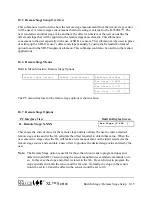
the data source for the encoder output. For example the stage value from the built-in pressure
transducer of the H-350CL could be used as the data source to calculate the quadrature output on
the two I/O pins. If this mode is selected, a stage measurement would be made as a reference
point immediately after scanning is enabled. At each scan, the new stage measurements will be
compared to this reference point and the difference will be used to determine how many counts
should be made on the I/O pins. The new stage measurement will be saved as the reference point
for the next scan. The quadrature output is increased 1 count for every 0.01 unit increase in the
stage measurement.
PC Interface View Built In Display Screen
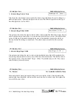
B - Trigger When = 0
Trg Fnt[0 ]
This option screen allows the user to view and edit the conditional statement used to determine if
the digital I/O pin should be set high when the selected digital I/O is configured as a triggered
output. By pressing enter, the user begins the editing process. The flashing cursor will indicate
the character position that may be edited. The user can use the RIGHT and LEFT arrow keys to
change to cursor position, and the UP and DOWN arrow keys to change the blinking character.
This statement is normally a logical expression that is true or false . For example, “ana1>10.0”
would equate to true if the value for analog channel 1 was greater than 10.0 and would equate to
false if it was less than or equal to 10.0. Logical expressions return a value of 1.0 if true and 0.0
if false. If the conditional statement is true the output will be triggered, (set or pulsed high).
The trigger condition is actually true for any value that is greater than 0.0 and is false for any
value that is 0.0 or less. This allows for standard math expressions to also be used for the trigger
condition. For example, if a temperature probe was connected to analog channel 1 that measured
temperature in degrees Fahrenheit, a math equation like “(ana1-32)*-1” could be used to turn on
a heater any time the temperature was below 32 degrees F. Any time the temperature was at or
above freezing (32 degrees) the result of the equation would be zero or negative and the
condition would be considered false, however, if the temperature was below freezing, the result
would be positive and the condition would be considered true.
The conditional statement can be up to 48 characters long and can be based on multiple
conditions as shown in the next example: “(ana1>10.0)&(counts>0.05)”. In this example the
value for analog channel 1 must be greater than 10.0
AND
the count input (normally rain fall)
must be greater than 0.05 for the condition to be considered true. The conditional statements
here use the same format and operators as the general purpose functions found in chapter 22.
Refer to chapter 21 for detailed instructions for editing the conditional statements, mathematical
and logical operators, variable names, etc. The functions and conditional statements are much
easier to edit and test using the PC menu mode interface.
Summary of Contents for H-350XL
Page 1: ...XL Series Models H 350XL H 500XL H 510XL H 522 H 522 Plus Owner s Manual ...
Page 30: ...2 16 Hardware Options and Installation XL Series ...
Page 42: ...3 12 Using The Built In Keypad Display XL Series ...
Page 46: ...4 4 PC Menu Interface Operation XL Series ...
Page 58: ...5 12 Miscellaneous System Setup XL Series ...
Page 66: ...6 8 Serial Port Options XL Series ...
Page 74: ...7 8 System Configuration Files XL Series ...
Page 84: ...8 10 System Status Menus Options XL Series ...
Page 88: ...9 4 Scanning Options XL Series ...
Page 156: ...15 12 Logging Options XL Series ...
Page 198: ...16 42 Operation with the GOES Radio XL Series ...
Page 216: ...19 6 Alarm Call Out XL Series ...
Page 234: ...21 8 Operation with the H 355 Smart Gas System XL Series ...
Page 246: ...22 12 Functions XL Series ...

