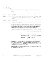
Power Management
7-8
Copyright © 2005-2008 ARM Limited. All rights reserved.
ARM DDI 0337G
Non-Confidential
Unrestricted Access
Figure 7-4 Power down timing sequence
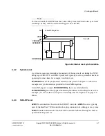
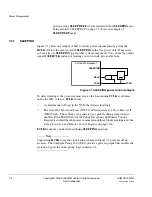
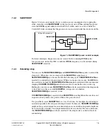
Figure 7-5 on page 7-9 shows an example PMU, WIC, and NVIC interconnection with
example clamp values for a system using state retention cells. The clamp values have
been set to the same value to ease integration. The location of the WICPEND and
interrupt OR gates is not important. The clamps are typically inserted by the tools
during synthesis.
SLEEPING
WICLOAD
SLEEPDEEP
WICMASK[]
WICCLEAR
nISOLATE
nRETAIN
PWRUP
WICINT[]
WAKEUP
WICPEND
FCLK
1) NVIC drives WICLOAD before entering deep sleep
2) Core enters deep sleep
The signals below demonstrate the core power-down sequence
3) PMU isolates core power domain
4) PMU drives core state retention
5) PMU powers down core
6) Un-masked interrupt arrives
7) Interrupt pended, WIC notifies PMU by asserting WAKEUP
8) PMU powers up core
9) PMU drives state restoration
10) PMU takes core out of isolation
11) Core sees incoming IRQ/NMI/RXEV
and asserts WICCLEAR
12) WIC pended interrupts
cleared and WAKEUP de-
asserted

