Trace Port Interface Unit
ARM DDI 0337G
Copyright © 2005-2008 ARM Limited. All rights reserved.
17-9
17.2.2
Description of the TPIU registers
This section describes the TPIU registers.
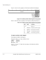
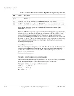
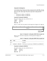
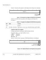
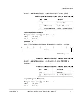
Supported Sync Port Sizes Register
This register is read/write. Each bit location represents a single port size that is
supported on the device, that is, 4, 2 or 1 in bit locations [3:0]. If the bit is set then that
port size is permitted. By default the RTL is designed to support all port sizes, set to
0x0000000B
. This register is constrained by the input tie-off
MAXPORTSIZE
. The
external tie-off,
MAXPORTSIZE
, must be set during finalization of the ASIC to
reflect the actual number of
TRACEDATA
signals wired to physical pins. This is to
ensure that tools do not attempt to select a port width that an attached TPA cannot
capture. The value on
MAXPORTSIZE
causes bits within the Supported Port Size
register that represent wider widths to be clear, that is, unsupported.
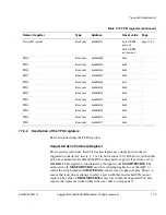
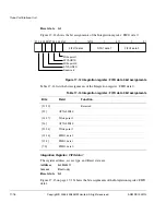
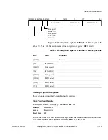
Device ID register
Read only
0xE0040FC8
0xCA0
(ETM
present)
0XCA1
(ETM
not present)
page 17-20
PID4
Read only
0xE0040FD0
0x04
-
PID5
Read only
0xE0040FD4
0x00
-
PID6
Read only
0xE0040FD8
0x00
-
PID7
Read only
0xE0040FDC
0x00
-
PID0
Read only
0xE0040FE0
0x23
-
PID1
Read only
0xE0040FE4
0xB9
-
PID2
Read only
0xE0040FE8
0x2B
-
PID3
Read only
0xE0040FEC
0x00
-
CID0
Read only
0xE0040FF0
0x0D
-
CID1
Read only
0xE0040FF4
0x90
-
CID2
Read only
0xE0040FF8
0x05
-
CID3
Read only
0xE0040FFC
0xB1
-
Table 17-5 TPIU registers (continued)
Name of register
Type
Address
Reset value
Page

