Parameter
06.042
Control Word
Short description
Controls the sequencer state machine inputs if the control word is enabled
Mode
Open
‑
loop
Minimum
0
(Display: 000000000000000)
Maximum
32767
(Display: 111111111111111)
Default
0
(Display: 000000000000000)
Units
Type
16 Bit Volatile
Update Rate
Bits 9,7-0: 4ms, Other bits:
Background read
Display Format
Binary
Decimal Places
0
Coding
RW, NC
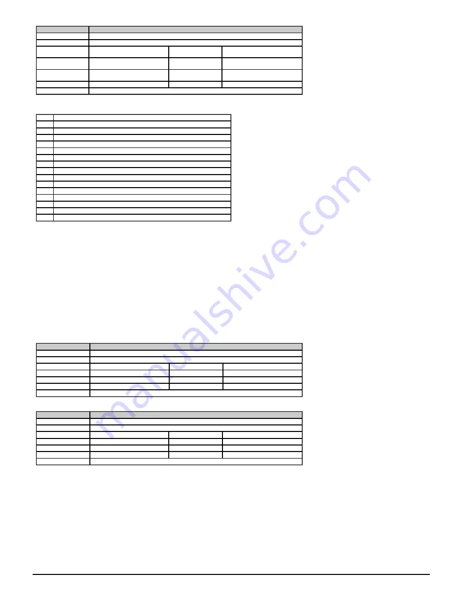
If
Control Word Enable
(06.043) = 0 then
Control Word
(06.042) has no effect. If
Control Word Enable
(06.043) = 1 the bits in
Control Word
(06.042) are used instead of their corresponding
parameters or to initiate drive functions as shown in the table below:
Bit
Corresponding paramter or function
0
Drive Enable
(06.015)
1
Run Forward
(06.030)
2
Jog Forward
(06.031)
3
Run Reverse
(06.032)
4
Forward/Reverse
(06.033)
5
Run
(06.034)
6
Not Stop
(06.039)
7
Auto / manual
8
Analog / Preset reference
9
Jog Reverse
(06.037)
10
Not used
11
Not used
12
Trip drive
13
Reset drive
14
Watchdog
Because of the limited number of segments on drives with an LED display, these drives will indicate the parameter value as a decimal value rather than a binary value.
Bits 0-7 and bit 9: Sequencer control
When Auto/manual bit (bit7) = 1 then bits 0 to 6 and bit 9 of the
Control Word
(06.042) become active. The equivalent parameters are not modified by these bits, but become inactive when the
equivalent bits in the
Control Word
(06.042) are active. When the bits are active they replace the functions of the equivalent parameters.
Bit 8: Analogue/preset reference
The state of Analogue/Preset Reference (bit 8) is written continuously to
Reference Select Flag 2
(01.042). With default drive settings (i.e.
Reference Selector
(01.014) = 0) this selects
Analog Reference 1
(01.036) when bit 8 = 0 or
Preset Reference 1
(01.021) when bit8 = 1. If any other drive parameters are routed to
Reference Select Flag 2
(01.042) the value of this
parameter is undefined.
Bit 10 and bit 11: Not used
The values of these bits have no effect on the drive.
Bit 12: Trip drive
If bit 12 = 1 then a
Control Word
trip is repeatedly initiated. The trip cannot be cleared until bit 12 = 0.
Bit 13: Reset drive
If bit 13 is changed from 0 to 1 a drive reset is initiated. Bit 13 does not modify
Drive Reset
(10.033).
Bit 14: Watchdog
A watchdog system can be enabled or serviced each time bit 14 is changed from 0 to 1. Once bit 14 has been changed from 0 to 1 to enable the watchdog, this must be repeated every 1s or
else a
Watchdog
trip will be initiated. The watchdog is disabled when the trip occurs and must be re-enabled if required when the trip is reset.
Parameter
06.043
Control Word Enable
Short description
Set to 1 to enable the control word
Mode
Open
‑
loop
Minimum
0
Maximum
1
Default
0
Units
Type
8 Bit User Save
Update Rate
4ms
Display Format
Standard
Decimal Places
0
Coding
RW
See
Control Word
(06.042).
Parameter
06.045
Cooling Fan control
Short description
Defines the maximum speed of the drive cooling fan
Mode
Open
‑
loop
Minimum
0
Maximum
5
Default
2
Units
Type
8 Bit User Save
Update Rate
Background read
Display Format
Standard
Decimal Places
0
Coding
RW
Note: Size 1 drives only have a single fan speed and so some of the operational modes are not available.
If
Cooling Fan control
(06.045) = 0 the cooling fan in the drive is off.
Some option modules consume more power than others and so if one of the higher power consumption modules is fitted to the drive, the drive will trip
OHt Control
if
Stack Temperature
(07.004) is above an internally set threshold (drive power rating dependant), and the option module will be forced to go into standby.
If
Cooling Fan control
(06.045) = 1 the cooling fan in the drive is forced to run at full speed.
If
Cooling Fan control
(06.045) = 2 the cooling fan in the drive is controlled by the values of
Stack Temperature
(07.004) and
Current Magnitude
(04.001) . The fan will run at full speed for at
least 20 seconds if
Stack Temperature
(07.004) is greater than a frame dependent threshold (60 °C for size 1 & 2 or 50 °C for size 3 & 4) or
Current Magnitude
(04.001) is greater than 75%
of
Drive current rating
(11.068), otherwise the cooling fan is off. If neither of the above conditions are causing the fan to run, the fan will run at low speed if one of the higher power consumption
option modules is fitted and
Stack Temperature
(07.004) is above the internally set threshold. The fan will not turn off until
Stack Temperature
(07.004) falls to 5°C below the internally set
threshold.
If
Cooling Fan control
(06.045) = 3 is the same as
Cooling Fan control
(06.045) = 2 but the cooling fan never turns off but runs at low speed when full speed is not being called for. This mode is
not available on size 1 and so if selected, mode 2 is used instead.
If
Cooling Fan control
(06.045) = 4 the cooling fan in the drive is at low speed continuously. This mode is not available on size 1 and so if selected, mode 1 is used instead.
94
Unidrive M200 Parameter Reference Guide
Issue: 01.05.00.10
Summary of Contents for unidrive m200
Page 1: ...Parameter Reference Guide Unidrive M200 Open loop Mode Issue 01 05 00 10 ...
Page 30: ...30 Unidrive M200 Parameter Reference Guide Issue 01 05 00 10 ...
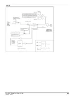
Page 83: ...Enable logic Unidrive M200 Parameter Reference Guide Issue 01 05 00 10 83 ...
Page 125: ...Unidrive M200 Parameter Reference Guide Issue 01 05 00 10 125 ...
Page 145: ...Unidrive M200 Parameter Reference Guide Issue 01 05 00 10 145 ...
Page 204: ...204 Unidrive M200 Parameter Reference Guide Issue 01 05 00 10 ...

