If
Cooling Fan control
(06.045) = 5 is the same as
Cooling Fan control
(06.045) = 2 but with an additional lower temperature threshold that causes the fan to run at low speed if
Stack Temperature
(07.004) is above the lower threshold - “theatre mode”. In some applications this may prevent the fan running at full speed and so keep the audible noise down to a
minimum. This mode is not available on size 1 and so if selected, mode 2 is used instead.
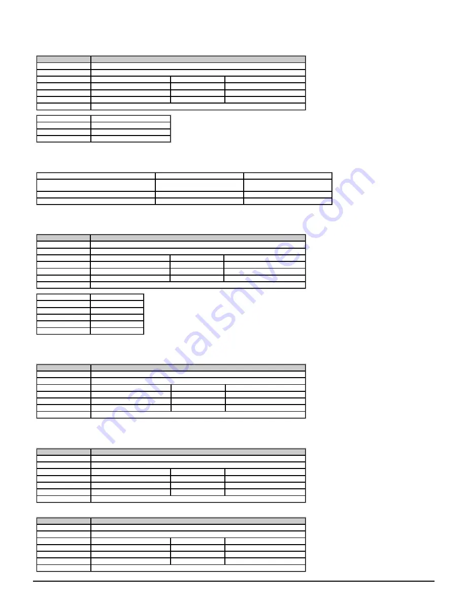
Parameter
06.047
Input Phase Loss Detection Mode
Short description
Defines how the input phase loss is detected
Mode
Open
‑
loop
Minimum
0
Maximum
2
Default
0
Units
Type
8 Bit User Save
Update Rate
Background read
Display Format
Standard
Decimal Places
0
Coding
RW, TE
Value
Text
0
Full
1
RIPPLE
2
diS
Input phase loss is detected by monitoring the d.c. link voltage ripple which increases with load. When compared to normal operation, if an input phase is missing or there is excessive input
phase imbalance the d.c. link ripple level is higher. The high ripple level is detected to initiate a
PH.Lo
trip. For drive sizes 8 and above an additional input phase loss detection is provided by
direct monitoring of the supply voltages (
PH.Lo
trip). Unlike the d.c. voltage ripple based detection which can only operate when the drive is enabled and on load, the additional input phase loss
detection can operate whether the drive is enabled or not.
Input Phase Loss Detection Mode
(06.047) defines the methods used for input phase loss detection provided by the drive.
Input Phase Loss Detection Mode
(06.047)
Drive Active
(10.002) = 0
Drive Active
(10.002) = 1
0
*Direct input phase loss detection
*Direct input phase loss detection
D.c. link voltage ripple detection
1
*Direct input phase loss detection
D.c. link voltage ripple detection
2
No input phase loss detection
No input phase loss detection
*Frame sizes 8 and above
Input phase loss detection can be disabled when the drive is required to operate from a d.c. supply connected to the d.c. link or from a single phase supply. If the drive operates from a single
phase supply or a supply with high levels of phase imbalanced under load the input stage and d.c. link thermal protection system may produce a
OHt dc bus
trip.
Parameter
06.048
Supply Loss Detection Level
Short description
Defines the threshold for indicating when the supply loss condition is detected
Mode
Open
‑
loop
Minimum
0
Maximum
VM_SUPPLY_LOSS_LEVEL
Default
See exceptions below
Units
V
Type
16 Bit User Save
Update Rate
Background read
Display Format
Standard
Decimal Places
0
Coding
RW, VM, RA
Voltage
Default Value
110V
205
200V
205
400V
410
575V
540
690V
540
Defines the threshold for indicating when the supply loss condition is detected.
The threshold can be adjusted to higher levels using this parameter. If the value is reduced below the default value the default value is used by the drive. If the level is set too high so that supply
loss detection becomes active under normal operating conditions, the motor will coast to a stop.
Parameter
06.051
Hold Supply Loss Active
Short description
Hold Supply Loss Active
Mode
Open
‑
loop
Minimum
0
Maximum
1
Default
0
Units
Type
1 Bit Volatile
Update Rate
1ms read
Display Format
Standard
Decimal Places
0
Coding
RW, NC
If supply loss is detected (i.e.
Supply Loss
(10.015) = 1) or
Hold Supply Loss Active
(06.051) = 1 the supply loss indication and the action taken on supply loss will be active. For
example,
Hold Supply Loss Active
(06.051) can be controlled by an external rectifier or a Regen system (via a digital input) to prevent power from being taken from the supply if supply loss ride-
through mode is being used until the input system is ready to provide power. This can allow for the charge system in an external rectifier to complete the charging, or it can allow a Regen
system to become synchronised.
Parameter
06.052
Motor Pre-heat Current Magnitude
Short description
Defines the current in the motor when the state machine is in the stop state
Mode
Open
‑
loop
Minimum
0
Maximum
100
Default
0
Units
%
Type
8 Bit User Save
Update Rate
Background read
Display Format
Standard
Decimal Places
0
Coding
RW
See
Hold Zero Frequency
(06.008).
Parameter
06.058
Output Phase Loss Detection Time
Short description
Output Phase Loss Detection Time
Mode
Open
‑
loop
Minimum
0
Maximum
3
Default
0
Units
Type
8 Bit User Save
Update Rate
Background read
Display Format
Standard
Decimal Places
0
Coding
RW, TE
Unidrive M200 Parameter Reference Guide
Issue: 01.05.00.10
95
Summary of Contents for unidrive m200
Page 1: ...Parameter Reference Guide Unidrive M200 Open loop Mode Issue 01 05 00 10 ...
Page 30: ...30 Unidrive M200 Parameter Reference Guide Issue 01 05 00 10 ...
Page 83: ...Enable logic Unidrive M200 Parameter Reference Guide Issue 01 05 00 10 83 ...
Page 125: ...Unidrive M200 Parameter Reference Guide Issue 01 05 00 10 125 ...
Page 145: ...Unidrive M200 Parameter Reference Guide Issue 01 05 00 10 145 ...
Page 204: ...204 Unidrive M200 Parameter Reference Guide Issue 01 05 00 10 ...

