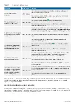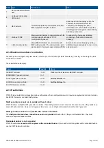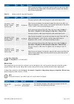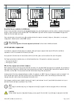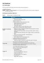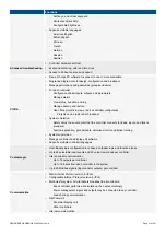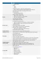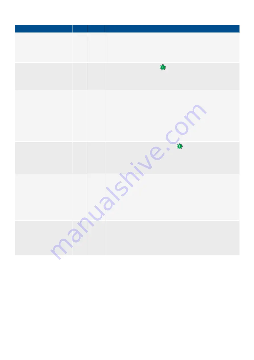
Table 2.1
Commands to start sequences
Command
Mode Type
Example
The controller starts the
sequence.
AUTO Internal
The controller parameters are set so that the controller starts the genset
when the available power is too low.
The controller calculates that the available power is too low, and starts the
sequence to start the genset.
The operator presses a push-
button on the display unit.
SEMI External
The operator presses the
Start
button on the display unit.
The controller gets the command over the DEIF network, and starts the
sequence to start the genset.
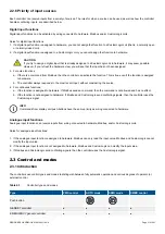
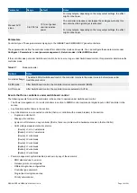
A digital input, which is assigned
an external command function,
is activated.
SEMI External
A button on the switchboard is wired to a digital input on IOM3.1 in slot 6
(terminals 22 and 23) of the controller rack. Under
Configure > Input/output
,
these terminals are assigned the
Engine > Command > Start engine
function.
The operator presses the button on the switchboard, to activate the digital
input.
The controller detects that the digital input is activated, and starts the
sequence to start the genset.
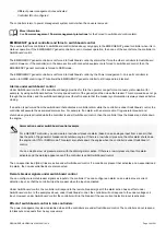
The operator selects a virtual
display unit push-button on the
Supervision
page in PICUS.
SEMI External
The operator presses the controller
Start
button on the
Supervision
page in PICUS.
The controller gets the command over the DEIF network, and starts the
sequence to start the genset.
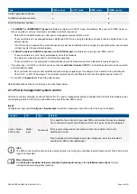
CustomLogic activates an
external command function.
SEMI External
A function is programmed in CustomLogic. The CustomLogic rung has the
conditions that need to be met. There is a
Normally open coil
with the
function
Engine > Command > Start engine
at the end of the rung.
The conditions are met, and CustomLogic activates the function.
The controller detects that the function is activated, and starts the sequence
to start the genset.
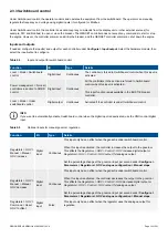
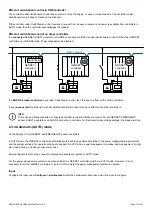
Using Modbus communication,
an operator, a SCADA system,
or a PLC sets a Modbus
address in the function group
Command
to
1
(True).
SEMI External
A PLC has a Modbus connection to the required controller. The PLC writes
1
(True) to Modbus address 1000 in the discrete output coil using the Modbus
function code 05 or 15.
The controller gets the command, and starts the sequence to start the
genset.
The controller ignores the command and displays an info message if the controller cannot execute the command. For example, if a
GENSET controller is under
Switchboard control
, it ignores a
Start engine
command. The controller displays the info message
Engine start not possible in SWBD
.
2.2.3 Understanding the system versatility
A number of controllers are used together to create a controller system. Each controller has configurable hardware, which in turn
has configurable inputs and outputs. The controller gets information from the measurements, the inputs, and the DEIF network. The
controller sends out information using the outputs, and the DEIF network.
DESIGNER'S HANDBOOK 4189340911K UK
Page 27 of 521


