Chapter 3
Analog Output Timing/Control
©
National Instruments Corporation
3-9
DAQ-STC Technical Reference Manual
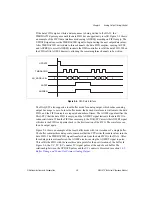
If the data FIFO empties while a data sequence is being written to the DACs, the
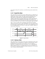
TMRDACWR pulses pause until the data FIFO has an opportunity to refill. Figure 3-5 shows
an example of the FIFO data interface mode using AOFREQ asserting on FIFO empty. The
UPDATE signal causes the TMRDACWR signal to begin writing the next output data values.
After TMRDACWR writes data to three channels, the data FIFO empties, causing AOFEF
and AOFREQ to assert. AOFREQ instructs the DMA controller to refill the data FIFO. When
the FIFO refills, AOFEF deasserts, allowing the remaining three channels to be written.
Figure 3-5.
FIFO Data Interface
The DAQ-STC also supports a local buffer mode for analog output, which reduces analog
output bus usage to zero. In local buffer mode, the desired waveform is written into the data
FIFO, and the FIFO contents are repeated a number of times. The AOFEF signal notifies the
DAQ-STC that the data FIFO is empty, and the AOFFRT signal instructs the data FIFO to
retransmit its data. When the FIFO becomes empty, the DAQ-STC asserts the AOFFRT signal
which sets the FIFO read pointer back to the first location of the FIFO. The waveform can
then be output again.
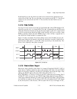
Figure 3-6 shows an example of the local buffer mode with two iterations of a single buffer.
The buffer contains three data points, so assume that the CPU writes three data values into the
data FIFO. The TMRDACWR signal transfers data from the data FIFO to the DACs. After
three data points are transferred, the AOFEF asserts, causing the AOFFRT signal to pulse.
This refills the FIFO with the same three data points for the next iteration of the buffer. In
Figure 3-6, the UC_TC (UC counter TC) signal pulses at the end of each buffer. The
relationship between the UPDATE pulses and the UC counter is discussed in section
Buffer Timing and Control for Primary Analog Output
.
AOFEF
AOFREQ
AO_ADDR<3..0>
UPDATE
TMRDACWR
0
1
2
3
4
0
5


