Chapter 7
Digital I/O
DAQ-STC Technical Reference Manual
7-4
©
National Instruments Corporation
7.4.2 Serial Mode
In serial mode, the DAQ-STC exchanges 8-bit wide data with an external device through two
serial pins, one for each direction. Three sources are available for timing the serial data
transfers—a 1.2
µ
s clock, a 10
µ
s clock, and a software-controlled clock. The external device
receives timing from the DAQ-STC through the output EXTSTROBE/SDCLK.
7.4.2.1 Serial Input
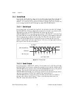
In serial input mode, an external device transfers 8-bit serial data to the DAQ-STC through
the DIO4/SDIN line. Software configures the external device to place a new data bit on the
DIO4/SDIN line after each EXTSTROBE/SDCLK falling edge and selects
EXTSTROBE/SDCLK to be one of the periodic timebases. The DAQ-STC clocks data from
the DIO4/SDIN line on each EXTSTROBE/SDCLK rising edge. This arrangement allows the
data line adequate time to stabilize before reading. The DAQ-STC only generates enough
pulses on EXTSTROBE/SDCLK to complete the current 8-bit data transfer. Each 8-bit
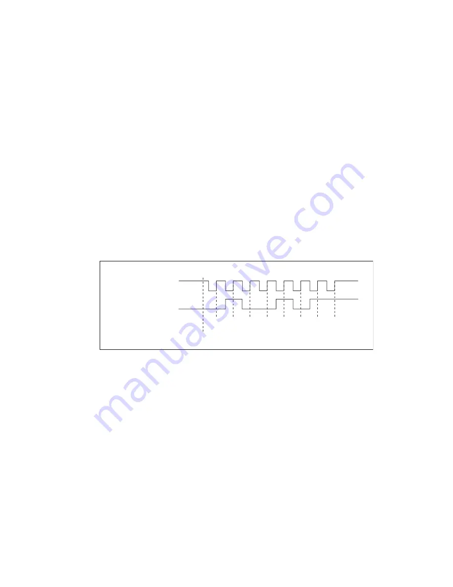
transfer is initiated under software control. Figure 7-4 shows a serial input operation where
the DAQ-STC reads the data byte 0x4B hex.
Figure 7-4.
DIO Serial Input
7.4.2.2 Serial Output
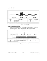
In serial output mode, the DAQ-STC transfers 8-bit serial data to an external device through
the DIO0/SDOUT line. Software configures the external device to read a new data bit on each
EXTSTROBE/SDCLK rising edge and selects EXTSTROBE/SDCLK as one of the periodic
timebases. The DAQ-STC places new data on the DIO0/SDOUT line every
EXTSTROBE/SDCLK falling edge. This arrangement allows the data line adequate time to
stabilize before reading. The DAQ-STC generates only enough pulses on
EXTSTROBE/SDCLK to complete the current 8-bit data transfer. Each 8-bit transfer is
initiated under software control. Figure 7-5 shows a serial input operation where the
DAQ-STC outputs the data byte 0x4B hex.
EXTSTROBE/SDCLK
DIO4/SDIN
Read Locations
Input Pattern: 0x4B
R
R
R
R
R
R
R
R
SW START


