Chapter 2
Analog Input Timing/Control
DAQ-STC Technical Reference Manual
2-28
©
National Instruments Corporation
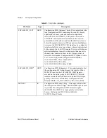
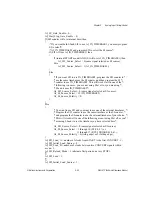
AI_CONVERT_Pulse_Width = 0 (1.5–2 AI_OUT_TIMEBASE periods) or
1 (0.5–1 AI_OUT_TIMEBASE periods);
AI_CONVERT_Output_Select = 0 (high Z) or 1 (ground) or 2 (enable, active low) or
3 (enable, active high);
AI_FIFO_Flags_Polarity = 0 (active low) or 1 (active high);
AI_LOCALMUXCLK_Pulse_Width = 0 (Retransmit = 0.5–1 AI_OUT_TIMEBASE
periods, Read = 1.5–2 AI_OUT_TIMEBASE periods) or
1 (Retransmit = 0.5 AI output clock periods,
Read = 0.5–1 AI_OUT_TIMEBASE periods);
AI_AIFREQ_Polarity = 0 (active high) or 1 (active low);
AI_SC_TC_Output_Select = 0 (high Z) or 1 (ground) or 2 (enable, active low) or 3
(enable, active high);
AI_SHIFTIN_Polarity = 0 (active low) or 1 (active high);
AI_SHIFTIN_Pulse_Width = 0 (0.5–1.5 AI_OUT_TIMEBASE periods) or
1 (1.5–2 AI_OUT_TIMEBASE periods);
AI_EOC_Polarity = 0 (rising edge) or 1 (falling edge);
AI_SOC_Polarity = 0 (rising edge) or 1 (falling edge);
AI_Overrun_Mode = 0 (from SOC to EOC) or 1 (from SOC to the trailing edge of
SHIFTIN);
AI_SCAN_IN_PROG Output_Select = 0 (high Z) or 1 (ground) or 2 (enable, active low)
or 3 (enable, active high);
AI_LOCALMUX_CLK_Output_Select = 0 (high Z) or 1 (ground) or 2 (enable, active
low) or 3 (enable, active high);
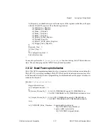
∑
AI_Configuration_End = 1;
End critical section;
}
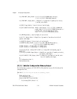
2.6.3.3 Initialize Configuration Memory Output
Use this function to generate a LOCALMUX_CLK pulse that accesses the first value in the
configuration FIFO.
Function
AI_Initialize_Configuration_Memory_Output
{
Begin critical section;
AI_Configuration_Start = 1;
If (an external MUX is present) then
{
AI_External_MUX_Present = 0;


