Chapter 7
Digital I/O
©
National Instruments Corporation
7-15
DAQ-STC Technical Reference Manual
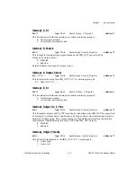
DIO_Serial_IO_In_Progress_St
bit: 12
type: Read
in: Joint_Status_1_Register
address: 27
This bit indicates whether the first seven bits of serial digital I/O is in progress:
0: Indicates that operation is not in progress, or that the last bit is being shifted out.
1: Indicates that one of the first seven bits is being shifted out.
Note that after this bit changes from 1 to 0 there is still one more bit of data to be shifted in/out.
You must wait one more serial clock period for the operation to finish, which, for example,
can be performed by a software delay loop or OS provided function.
DIO_Serial_Out_Divide_By_2
bit: 13
type: Write
in: Clock_and_FOUT_Register
address: 56
Divide the clock used for serial digital I/O timing by 2, provided hardware timing is used:
0: No. SERIAL_TIMEBASE is IN_TIMEBASE.
1: Yes. SERIAL_TIMEBASE is IN_TIMEBASE divided by 2.
DIO_Software_Serial_Control
bit: 11
type: Write
in: DIO_Control_Register
address: 11
If DIO_HW_Serial_Enable is set to 0, the inverted state of this bit is reflected on the
EXTSTROBE/SDCLK pin.
Generic_Status
bits: <8..11>
type: Read
in: Joint_Status_2_Register
address: 29
This bitfield reflects the value of the STATUS<0..3> pins.
7.7 Timing Diagrams
This section presents the timing for the serial DIO mode.
7.7.1 Serial Input Timing
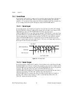
In the serial-input mode, the rising edge of the EXTSTROBE/SDCLK signal clocks data on
the DIO4/SDIN line. Figure 7-7 shows the setup and hold times for serial input.


