Chapter 2
Analog Input Timing/Control
©
National Instruments Corporation
2-59
DAQ-STC Technical Reference Manual
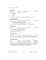
AI_FIFO_Second_Irq_Enable
bit: 7
type: Write
in: Second_Irq_A_Enable_Register
address: 74
This bit enables the FIFO interrupt in the secondary interrupt bank:
0: Disabled.
1: Enabled.
The FIFO interrupt is generated on the FIFO condition indicated by AI_FIFO_Mode. Related
bitfields: AI_FIFO_Mode.
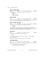
AI_Last_Shiftin_St
bit: 15
type: Read
in: Joint_Status_1_Register
address: 27
This bit indicates that the last SHIFTIN of the acquisition has occurred. The bit is set on the
SHIFTIN following the SC_TC trailing edge. It is cleared by setting
AI_SC_TC_Interrupt_Ack to 1. Related bitfields: AI_SC_TC_Interrupt_Ack.
Note
If the SC_CLK is slow with respect to the conversion period, the trailing edge of
SC_TC may miss the SHIFTIN pulse. This can happen in the internal CONVERT
mode if you select IN_TIMEBASE2 as the SI2 source. For this reason, you must
not rely on this bit as an end of acquisition indicator.
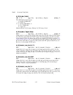
AI_LOCALMUX_CLK_Output_Select
bits: <4..5>
type: Write
in: AI_Output_Control_Register
address: 60
The bitfield enables and selects the polarity of the LOCALMUX_CLK output signal:
0: High Z.
1: Ground.
2: Enable, active low.
3: Enable, active high.
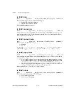
AI_LOCALMUX_CLK_Pulse
bit: 2
type: Strobe
in: AI_Command_1_Register
address: 8
Setting this bit to 1 produces a pulse on the LOCALMUX_CLK output signal, if the output
is enabled. The pulsewidth of the output signal is determined by
AI_LOCALMUX_CLK_Pulse_Width. LOCALMUX_CLK must also be cleared by an SOC.
This bit is cleared automatically. Related bitfields: AI_LOCALMUX_CLK_Output_Select,
AI_LOCALMUX_CLK_Pulse_Width
AI_LOCALMUX_CLK_Pulse_Width
bit: 5
type: Write
in: AI_Personal_Register
address: 77
This bit selects the pulsewidth of the LOCALMUX_FFRT output signal and the minimum
pulsewidth of the LOCALMUX_CLK output signal:
0: LOCALMUX_FFRT is 0.5–1 AI_OUT_TIMEBASE periods and


