Chapter 2
Analog Input Timing/Control
©
National Instruments Corporation
2-45
DAQ-STC Technical Reference Manual
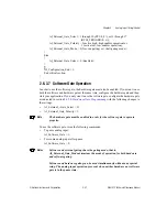
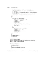
AI_SC_Load_B =
sc_ticks
[
si_ticks_pointer
] - 1;
AI_SI_Switch_Load_On_SC_TC = 1;
AI_SC_Switch_Load_On_TC = 1;
}
si_ticks_pointer
+ = 1;
si_last_load_register
= 1;
}
Else
{
AI_SI_Load_A =
si_ticks
[
si_ticks_pointer
] - 1;
If (
sc_ticks
[
sc_ticks_pointer
] is 0) then
{
AI_End_On_SC_TC = 1;
AI_SC_TC_Interrupt_Enable = 0;
}
Else
{
AI_SC_Load_A =
sc_ticks
[
si_ticks_pointer
] - 1;
AI_SI_Switch_Load_On_SC_TC = 1;
AI_SC_Switch_Load_On_TC = 1;
}
si_ticks_pointer
+ = 1;
si_last_load_register
= 0;
}
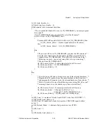
AI_SC_TC_Interrupt_Ack = 1;
/*Check for interrupt latency problems*/
If (AI_SC_TC_Error_St is 0) then
{
AI_SC_TC_Error_Confirm = 1;
}
Else
{
Inform user that an SC_TC error has occurred;
}
}
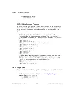
2.6.7 Master/Slave Operation Considerations
You can use several DAQ-STCs for synchronized analog input operation. To do this, connect
the trigger signal to the trigger input of the master DAQ-STC. You also connect the output
equivalents of the triggers from the master DAQ-STC to the slave DAQ-STCs. You may use
the RTSI connector to do this.
Note
You must perform the programming sequence described in section
Programming Clock Distribution
, before you execute the sequence given here.

