Chapter 2
Analog Input Timing/Control
©
National Instruments Corporation
2-61
DAQ-STC Technical Reference Manual
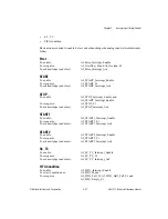
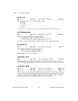
AI_Pre_Trigger
bit: 13
type: Write
in: AI_Mode_2_Register
address: 13
If AI_Continuous is 0, this bit selects between the posttrigger acquisition mode and the
pretrigger acquisition mode:
0: Posttrigger acquisition mode.
1: Pretrigger acquisition mode.
If AI_Continuous is 1, this bit is not used. Refer to section
2.4.3, Acquisition-Level Timing
, for more information on the acquisition modes. Related bitfields:
AI_Continuous.
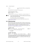
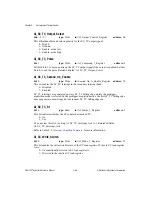
AI_Reset
bit: 0
type: Strobe
in: Joint_Reset_Register
address: 72
Setting this bit to 1 resets all the resetable registers to their power-on state. The resetable
registers are:
• AI_Command_1_Register
• AI_Command_2_Register
• AI_Mode_1_Register
• AI_Mode_2_Register
• AI_Mode_3_Register
• AI_Output_Control_Register
• AI_Personal_Register
• AI_START_STOP_Select_Register
• AI_Trigger_Select_Register
Setting this bit to 1 also clears all the status bits and interrupts related to AI, except those
associated with the AI data FIFO. This bit is cleared automatically.
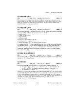
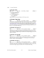
AI_Scan_In_Progress_St
bit: 7
type: Read
in: Joint_Status_2_Register
address: 29
This bit indicates whether a scan is currently in progress. The bit is set when a valid START
is received and the bit is cleared when a valid STOP is received.
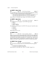
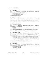
AI_SCAN_IN_PROG_Output_Select
bits: <8..9>
type: Write
in: AI_Output_Control_Register
address: 60
This bitfield enables and selects the polarity of the SCAN_IN_PROG output signal:
0: High Z.
1: Ground.
2: Enable, active low.
3: Enable, active high.

