Chapter 3
Analog Output Timing/Control
DAQ-STC Technical Reference Manual
3-112
©
National Instruments Corporation
SCKG
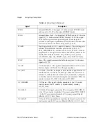
Internal UPDATE—This signal is 1 in the external UPDATE mode
and is equal to UI_TC in the internal UPDATE mode.
SCLK
Internal Update Clock—In the internal UPDATE mode, SCLK is the
signal UI_TC. In the external UPDATE mode, SCLK is the signal
FSCLK after it passes through a delay gate. The delay gate is
provided so that signals synchronized to FSCLK have sufficient time
to settle to a known state before being used by SCLK.
START1
Start Trigger for the UI, UC, and BC Counters—The start trigger is
software selectable from the either polarity of the PFI<0..9>,
RTSI_TRIGGER<0..6>, software strobe, or AI_START1. It can be
programmed to be edge or level sensitive and can be synchronized to
the BC_SRC. Related bitfields: AO_START1_Source_Select,
AO_START1_Edge, AO_START1_Sync, AO_START1_Polarity.
STOP
Stop—This signal terminates the buffer in progress. It is the same
signal as UC_TC.
UC_CE
UC Count Enable—This signal enables and disables the UC counter.
Refer to Figure 3-38 for the UC_CE logic equations.
UC_CLK
UC Clock—The UC clock signal is the actual clock signal for the UC
counter and the UC counter control logic. When the counter is not
armed, UC_CLK is the write strobe for AO_Command_1_Register,
so that the counter can be loaded using the load command. When the
counter is armed, UC_CLK is the same as BC_SRC.
UC_DISARM
UC Disarm—This signal, which is generated by the UC control
circuit, disarms the UC counter by asynchronously clearing
AO_UC_Arm.
UC_HOLD
UC Hold—This signal controls the UC save register. If UC_HOLD =
0, the UC save register tracks the UC counter output. If UC_HOLD
= 1, the UC save register latches the UC counter output. Related
bitfields: AO_UC_Save_Trace.
UC_LOAD
UC Load—This signal pulses to load the value from the selected UC
load register into the UC counter. Related bitfields: AO_UC_Load.
Table 3-6.
Internal Signals (Continued)
Signal
Description

