Chapter 3
Analog Output Timing/Control
DAQ-STC Technical Reference Manual
3-10
©
National Instruments Corporation
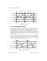
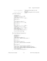
Figure 3-6.
Local Buffer Mode
3.4.3.2 Serial Link Data Interface
In the serial link data interface mode, the DACs receive analog output data through a serial
data link (or some other interface) instead of through the analog output data FIFO. In this
mode, the AOFEF signal is controlled by the data link. When AOFEF is active, the
TMRDACREQ signal asserts in place of the write signal TMRDACWR, indicating that data
is required for a DAC write operation. The assertion of TMRDACREQ initiates a transfer
across the data link. Once the transfer completes, the AOFEF signal is released, allowing the
DAC write to complete.
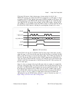
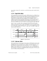
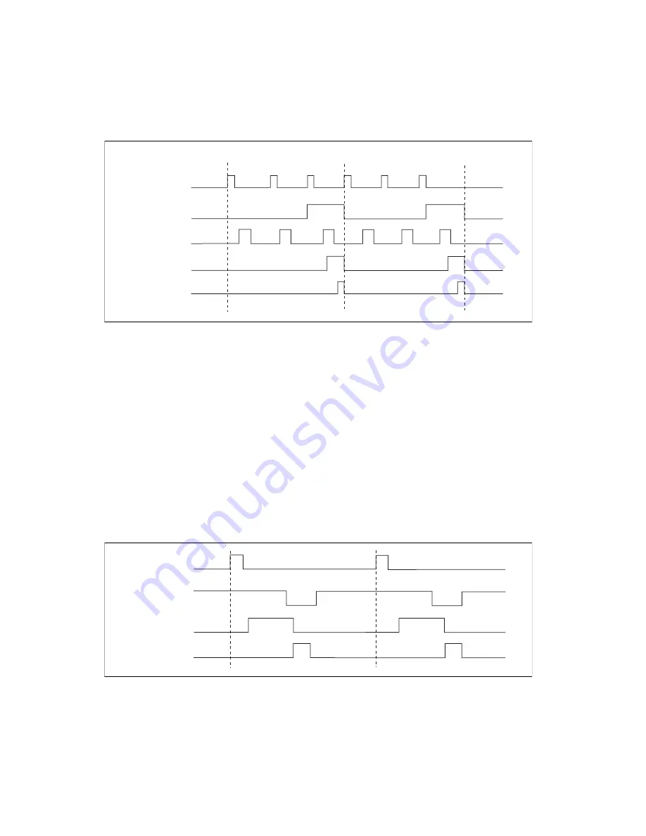
Figure 3-7 shows an example waveform from a serial link data interface. AOFEF is initially
held active. After the UPDATE pulse, TMRDACREQ is asserted where the TMRDACWR
pulse should be, causing the serial data link to transmit data. Once the serial link data transfer
completes, AOFEF is released, allowing the write to occur.
Figure 3-7.
Serial Link Data Interface
UPDATE
UC_TC
AOFEF
AOFFRT
Iteration 1
Iteration 2
TMRDACWR
UPDATE
AOFEF
TMRDACREQ
TMRDACWR


