Chapter 3
Analog Output Timing/Control
DAQ-STC Technical Reference Manual
3-118
©
National Instruments Corporation
3.8.3.2 UI Control
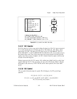
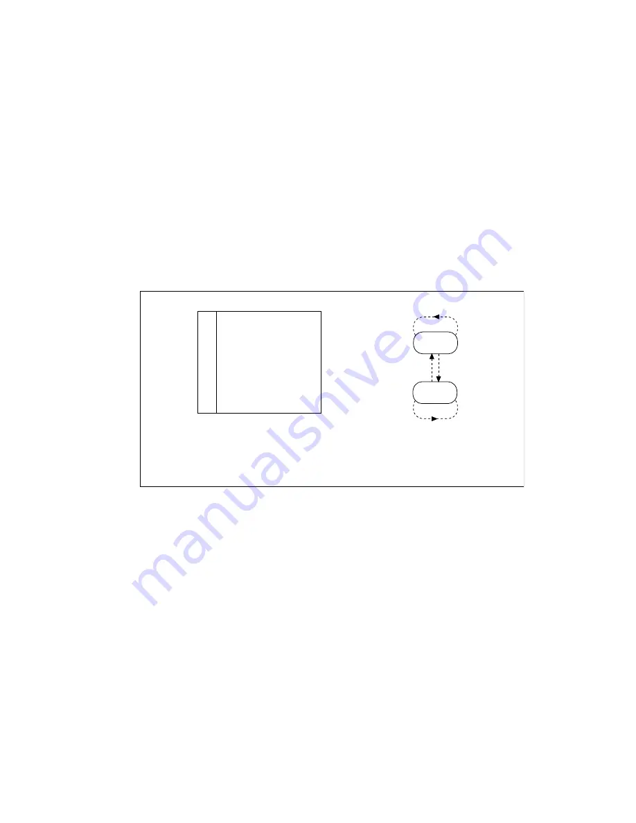
The UI counter is controlled by a circuit whose state transitions are shown in Figure 3-37. The
UI counter control circuit has two states, WAIT and CNT. On power up, the control circuit
begins and remains in state WAIT until the counter is armed and a START1 pulse is received.
The control circuit then transitions to state CNT and remains there until the count termination
condition is reached.
For continuous output modes, the UI counter control circuit can return to state WAIT based
on the software strobes AO_End_On_BC_TC and AO_End_On_UC_TC. Also, the UI
counter normally remains armed and retriggerable at the end of a scan sequence. The UI
counter has the option AO_Trigger_Once to disarm itself when returning to the WAIT state.
Figure 3-37.
UI Control Circuit State Transitions
3.8.3.3 UC Counter
The UC counter is a 24-bit down counter with dual-load registers and output save latch. The
UC counter typically counts the number of sample updates contained in a buffer. For this
reason, it is referred to as the update counter. The UC counter uses the same clock that is
selected for the BC counter BC_SRC. The counter load registers are directly accessible from
the register map. If the counter is disarmed, AO_UC_Load loads the counter with the value
from the selected load register.
During normal operation, the UC counter synchronously reloads from the selected load
register following UC_TC. Two options—AO_UC_Switch_Load_On_End and
AO_UC_Switch_Load_On_TC—change the selected load register under various conditions.
A
B
E
G
H
I
J
M
N
DA_START1
AO_UI_Arm
UI_TC
BC_TC
AO_End_On_BC_TC
AO_End_On_UC_TC
AO_Continuous
STOP
AO_Trigger_Once
T = G'H' + H'I'J
UI_LOAD = E + AO_UI_Load
UI_CE = CNT(n+1) AO_UI_Arm
UI_DISARM = CNT(n) WAIT(n+1) (H + I + N)
(AB)'
WAIT
CNT
AB
MET'
(MET')'


