Chapter 3
Analog Output Timing/Control
DAQ-STC Technical Reference Manual
3-116
©
National Instruments Corporation
Note
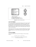
When the analog trigger circuit is enabled, the analog trigger signal takes over the
PFI0 slot in the PFI selectors.
3.8.2.1 Using Edge Detection
Use edge detection whenever a one-bit pulse is required but the pulsewidth of the trigger
signal cannot be guaranteed. Internally generated triggers are automatically the correct width
and need not be edge detected. Software strobes do not have the correct width and should
always be edge detected. Edge detection of external signals can usually be performed without
affecting the circuit operation.
3.8.2.2 Using Synchronization
Use synchronization whenever the trigger-to-clock timing relationship cannot be guaranteed.
Internally generated triggers automatically have the correct timing and need not be
synchronized. Software strobes do not have the correct timing and should always be
synchronized. Synchronization of external signals results in a one-half bit synchronization
delay.
3.8.2.3 Trigger Signals
START1 is the trigger for the waveform generation, initiating the output sequence. It can be
generated by software or by an external pulse. START1 can also be internally conditioned to
provide enhanced master/slave operation.
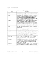
AO_UI_Source
AO_TB1
PFI<0..9>
RTSI<0..6>
—
TB2
—
GND
AO_UI2_Source
AO_TBL1
PFI<0..9>
RTSI<0..6>
G0_TC
G1_TC
TB2
GND
AO_UI_External_Gate
—
PFI<0..9>
RTSI<0..6>
—
—
—
GND
AO_UI2_External_Gate
—
PFI<0..9>
RTSI<0..6>
—
—
—
GND
Key:
AI_ST1
The internal analog input signal START1.
AO_TB1.
The internal analog output signal AO_IN_TIMEBASE1
G0_TC
The G_TC signal from general-purpose counter 0.
G1_TC
The G_TC signal from general-purpose counter 1.
GOUT1
The G_OUT signal from general-purpose counter 1.
SW
Software strobe
TB2
The internal signal IN_TIMEBASE2
Table 3-7.
PFI Selectors (Continued)
MUX
0
1–10
11–17
18
19
20
31

