Chapter 9
Bus Interface
©
National Instruments Corporation
9-3
DAQ-STC Technical Reference Manual
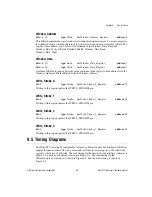
9.4 Programming Information
This section presents programming information that is specific to the bus interface. For
general information about programming the DAQ-STC, see section
.
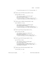
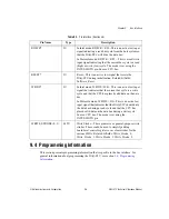
RD/WR*
IU
In Intel mode, RD/WR = RD—This is an active low input
signal indicating a read bus cycle from the host system so
that the DAQ-STC will drive the data bus.
In Motorola mode, RD/WR = R/W—This is a read/write
input signal indicating that the current bus cycle is a read
(high) or write (low) cycle. The mode is set using the
INTEL/MOTO pin. Source: CPU bus.
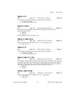
RESET*
IU
Reset—This is an active low signal that resets the
DAQ-STC during initialization. Related bitfields:
Software_Reset.
WR/DS*
IU
In Intel mode, WR/DS = WR—This is an active low input
signal that indicates that the current bus cycle is a write
cycle and that the CPU has placed valid data on the data
bus.
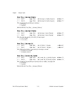
In Motorola mode, WR/DS = DS—This is an active low
input signal that indicates that the DAQ-STC should drive
the data bus during a read cycle and that the CPU has
placed valid data on the data bus during a write cycle.
Source: CPU bus. The mode is set using the
INTEL/MOTO pin.
WRITE_STROBE<0..3>
04TU
Write Strobe—These pins serve as general-purpose write
strobes. These could be used to simplify adding
board-level control registers or as clear strobes for the
various FIFOs. Related bitfields: Write_Strobe_0,
Write_Strobe_1, Write_Strobe_2, Write_Strobe_3.
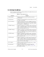
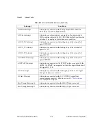
Table 9-1.
Pin Interface (Continued)
Pin Name
Type
Description

