Chapter 9
Bus Interface
DAQ-STC Technical Reference Manual
9-4
©
National Instruments Corporation
9.4.1 Programming the Write Strobes
Use the following function to pulse the write strobe signals WRITE_STROBE<0..3>.
Function
MSC_Write_Strobe
{
switch (strobe number)
{
case 0:
Write_Strobe_0 = 1;
break;
case 1:
Write_Strobe_1 = 1;
break;
case 2:
Write_Strobe_2 = 1;
break;
case 3:
Write_Strobe_3 = 1;
break;
}
}
Note
These are generic strobe lines. Refer to the hardware manual for your DAQ board
or device for information on how these lines are used.
9.4.2 Bitfield Descriptions
Bits in the register bit maps are organized into bitfields. A bitfield can contain one or more
bits. Only bits with contiguous locations within a register can belong to a bitfield. The high
and low pairs of load and save registers for 24-bit counters are also treated as bitfields. The
bus interface-related bitfields are described below. Not all bitfields referred to in section
, are listed here. To locate a particular bitfield description within
this manual, refer to Appendix B,
.
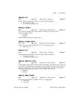
Software_Reset
bit: 11
type: Write
in: Joint_Reset_Register
address: 72
Setting this bit to 1 resets the DAQ-STC and is equivalent to pulsing the RESET pin. Setting
this bit to 0 clears the bit and takes the DAQ-STC out of reset. This bit cannot be cleared using
windowed mode accesses.
Software_Test
bit: 5
type: Strobe
in: Analog_Trigger_Etc_Register
address: 61
Setting this bit to 1 enables the hardware test mode, which tri-states all the output signals.
Setting this bit to 1 is equivalent to bringing the TEXT_IN pin low.

