Chapter 4
General-Purpose Counter/Timer
DAQ-STC Technical Reference Manual
4-46
©
National Instruments Corporation
G
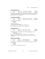
i_Permanent_Stale_Data_St
i = 0
bit: 14
type: Read
in: Joint_Status_2_Register
address: 29
i = 1
bit: 15
type: Read
in: Joint_Status_2_Register
address: 29
This bit indicates the detection of a permanent stale data error:
0: No error.
1: Error.
A permanent stale data error occurs if Gi_Stale_Data_St was set at any time during an
interrupt-driven noncumulative-event counting or period-measurement operation. This is
useful for after-the-fact error detection.
G
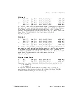
i_Read_Acknowledges_Irq
i = 0
bit: 0
type: Write
in: G0_Input_Select_Register
address: 36
i = 1
bit: 0
type: Write
in: G1_Input_Select_Register
address: 37
Setting this bit to 1 causes hardware save register accesses to clear Gi_Gate_Interrupt_St and
to reset the associated interrupt latency error-detection circuitry. To select between the
high/low save register, use Gi_Little_Big_Endian. Do not set this bit to 1 if
Gi_Write_Acknowledges_Irq is set to 1. Related bitfields: Gi_Gate_Interrupt_St,
Gi_Little_Big_Endian.
G
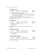
i_Reload_Source_Switching
i = 0
bit: 15
type: Write
in: G0_Mode_Register
address: 26
i = 1
bit: 15
type: Write
in: G1_Mode_Register
address: 27
If Gi_Gate_Select_Load_Source is set to 0, this bit enables load register selection in the
following manner:
0: Always use the same load register.
1: Alternate between the two load registers.
Related bitfields: Gi_Gate_Select_Load_Source.
G
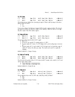
i_Reset
i = 0
bit: 2
type: Strobe
in: Joint_Reset_Register
address: 72
i = 1
bit: 3
type: Strobe
in: Joint_Reset_Register
address: 72
Setting this bit to 1 resets the counter, clears Gi_Arm and Gi_Arm_Copy, clears the
G0_Mode_Register, and clears the appropriate bits of the G_Input_Select_Register. This bit
is cleared automatically.

