Chapter 4
General-Purpose Counter/Timer
DAQ-STC Technical Reference Manual
4-80
©
National Instruments Corporation
4.8.11.10 Buffered Pulsewidth Measurement
To use this function, set G_CONTROL conditioning to level gating and program the counter
to reload on G_CONTROL and generate interrupts on G_GATE. The counter increments on
every G_SOURCE rising edge following the ARM. G_GATE is synchronized by the falling
edge of G_SOURCE to generate G_CONTROL. On the G_SOURCE rising edge following
G_CONTROL, the counter reloads from the selected load register. The HW save register
switches to transparent mode on the falling edge of G_GATE and returns to latched mode on
the next G_SOURCE falling edge.
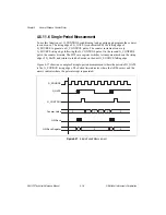
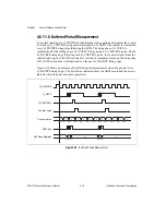
Figure 4-41 show an example of buffered pulsewidth measurement where the pulsewidth is
three G_SOURCE rising edges. The dotted line indicates where the ARM occurs and the
arrows indicate where the gate interrupt is generated. Figure 4-41 assumes that ARM occurs
while G_GATE is low. If ARM occurs while G_GATE is high, the initial pulse will only be
measured from ARM until the end of the pulse.
Figure 4-41.
Buffered Pulsewidth Measurement
Counter Value
Counter Load
G_SOURCE
G_GATE
G_CONTROL
HW Save
HW Save Register
2
3
1
2
3
4
5
1
2
3
4
5
1
3
3


