Chapter 4
General-Purpose Counter/Timer
DAQ-STC Technical Reference Manual
4-70
©
National Instruments Corporation
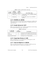
4.8.7.8 Disarm Counter on G_CONTROL
If Gi_Counting_Once is set to 2 or 3, the counter is disarmed following the G_CONTROL
transition that stops the counting.
4.8.7.9 Switch Load Bank Selection on G_CONTROL
If Gi_Bank_Switch_Enable is set to 1 and Gi_Bank_Switch_Mode is set to 0 and bank
switching has been started, an ACTIVE G_CONTROL selects bank X and an INACTIVE
G_CONTROL selects bank Y.
4.8.8 Interrupt Control
The GPCT module contains the hardware necessary for generating software interrupts based
on several conditions. The interrupt programming is accomplished using the
Interrupt_A_Enable_Register (general-purpose counter 0) and the
Interrupt_B_Enable_Register (general-purpose counter 1). Interrupts remain active until
cleared by software. Software can program the interrupts to occur under the following
conditions: assertion of counter TC and gate. Refer to Table 4-18 for a description of the gate
interrupt conditions.
4.8.9 PFI Selection
Table 4-19 summarizes the selections available for each of the trigger signals through the PFI
selector.
Table 4-19.
PFI Selectors
MUX
0
1–10
11–17
18
19
20
21
31
G0_Source
G_TB1
PFI<0..9>
RTSI<0..6>
TB2
G1_TC
GND
G0_Gate
PFI<0..9>
RTSI<0..6>
AI_ST2
UI2_TC
GOUT1
AI_ST1
GND
G1_Source
G_TB1
PFI<0..9>
RTSI<0..6>
TB2
G0_TC
GND
G1_Gate
PFI<0..9>
RTSI<0..6>
AI_ST2
UI2_TC
GOUT0
AI_ST1
GND
Key:
AI_ST1
The internal analog input signal START1.
AI_ST2
The internal analog input signal START1.
G0_TC
The G_TC signal from general-purpose counter 0.
G1_TC
The G_TC signal from general-purpose counter 1.
GOUT0
The G_OUT signal from general-purpose counter 0.
GOUT1
The G_OUT signal from general-purpose counter 1.
G_TB1
The internal signal G_IN_TIMEBASE1.
TB2
The internal signal IN_TIMEBASE2
UI2_TC
The internal analog output signal UI2_TC.


