Chapter 3
Analog Output Timing/Control
DAQ-STC Technical Reference Manual
3-20
©
National Instruments Corporation
3.6 Programming Information
This section presents programming information that is specific to the AOTM. For general
information about programming the DAQ-STC, see section
.
3.6.1 Programming for a Primary Analog Output Operation
This section contains detailed programming information for bit-level programming of the
primary AOTM for specialized applications. The programs are presented in a bottom-up
fashion. This section lists functions that can be used to configure the primary AOTM for
various operations. The functions are then assembled into a complete program in section
3.6.1.14, Primary Analog Output Program
.
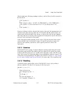
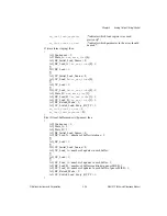
Most of the programming sequences presented here must be executed exactly as shown.
Bitfield assignment is a pseudocode instruction of the form <bitfield name> = <value>.
Pseudocode sequences enclosed in braces that contain only bitfield assignments can normally
be executed in any order, or simultaneously, if possible. If the sequence must be executed in
exact order, the character
∑
marks the boundary between two groups of assignments that have
to be executed sequentially. For example, in the following pseudocode, the first bitfield
assignment must be performed first; the second and third assignments may then be executed
in any order; but the fourth bitfield assignment must be executed after the second and third
UPDATE*
O9TU
Primary Update—This output is used to update the DACs. The
hardware generates UPDATE by passing the output of the
UPDATE selector (SCLK) through pulsewidth and polarity
selection circuitry. Output polarity is selectable. Destination:
DACs. Options: Active Low, Active High, Ground, High Z.
Related bitfields: AO_UPDATE_Output_Select,
AO_UPDATE_Pulse, AO_UPDATE_Original_Pulse,
AO_UPDATE_Pulse_Timebase, AO_UPDATE_Pulse_Width.
UPDATE2*
O9TU
Secondary Update—This output is the secondary update signal
to the DACs. The hardware generates UPDATE2 by passing the
internal UI2_TC (UI2 counter TC) signal through pulsewidth
and polarity selection circuitry. Output polarity is selectable.
Destination: DACs. Options: Active Low, Active High, Ground,
High Z. Related bitfields: AO_UPDATE2_Output_Select,
AO_UPDATE2_Output_Toggle, AO_UPDATE2_Pulse,
AO_UPDATE2_Original_Pulse,
AO_UPDATE2_Pulse_Timebase,
AO_UPDATE2_Pulse_Width.
Table 3-1.
Pin Interface (Continued)
Pin Name
Type
Description


