74
Note: Adds a set of logic switch. This is available for version 1.0.65 or above.
8.20 Logic switches
A logic switch is a virtual switch consisted of 2 switches which activates or deactivates according to a mathematical
relationship between the two. The system supports to set four groups of logic switches in total. There are three logic
difinations between two switches:
AND
,
OR
and
XOR
.
If there is any mathematical logic relationship between certain switch controls and the other two switch controls,
this function can be used to express this logic and use it as a logic switch in control. The logic switch can be selected
in any menu where switches can be assigned.
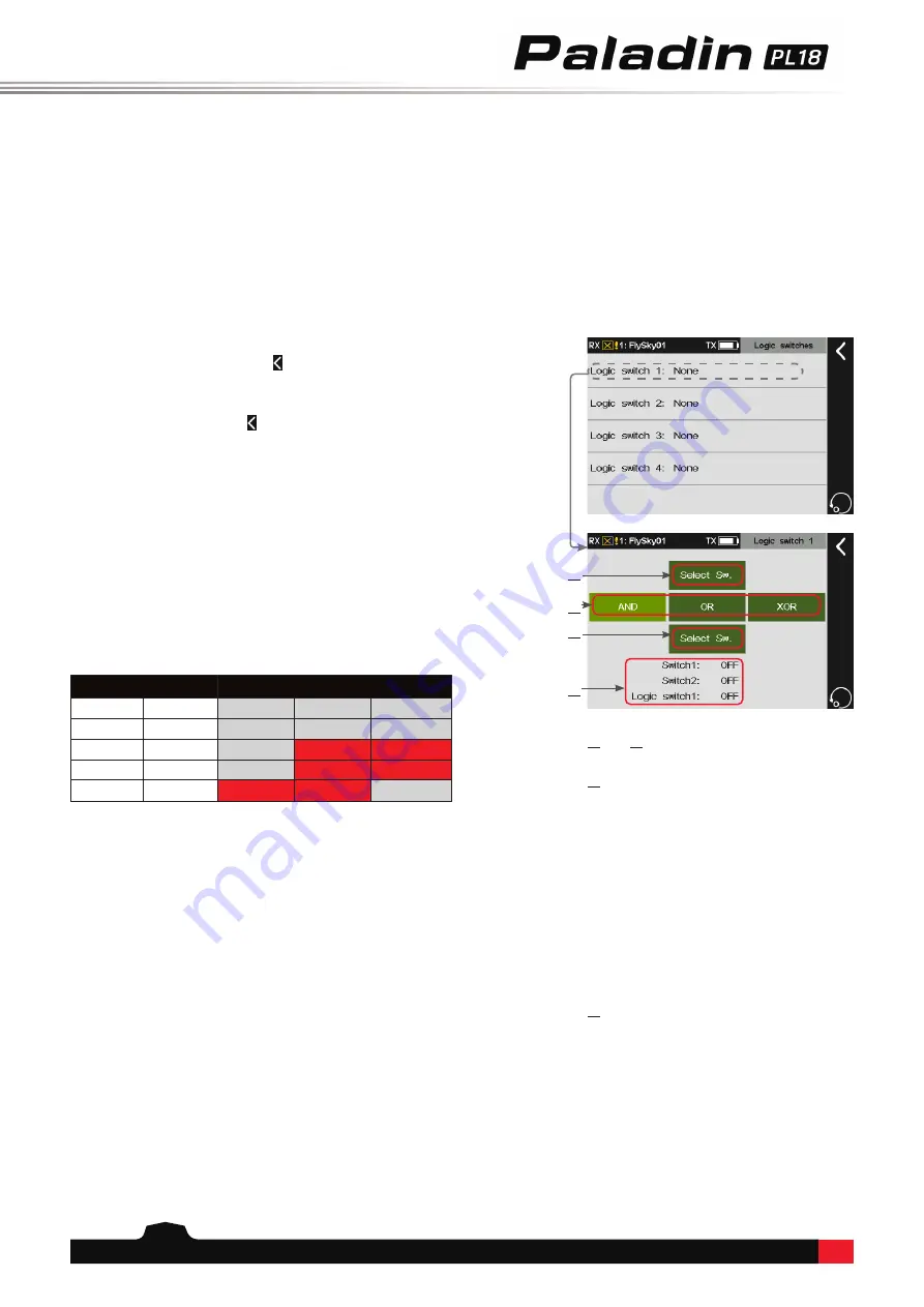
Function setup:
1. Tap a logic switch as you desire to set.
2. Tap the top
Select Sw.
to enter and click a switch
and its position, then click to return to the previous
interface.
3. Tap the bottom
Select Sw.
and click a switch and
its position, then click to return to the previous
interface.
4. Tap a logic difination you want to set:
AND
,
OR
or
XOR
. Refer to the following table for more
information on logic difinition and state.
5. Toggle the switches to make sure everything is
working as expected.
Notes:
1. The setting of a logic switch makes sense only if it is composed of
2 other different switches.
2. The system supports a logic switch is set up as a component
switch of other logic switches, two layers of logics at most, i.e., if
logic switch B is the component switch of logic switch A, then the
component switch of logic switch B must not be a logic switch.
Switch
Logic switch
Switch 1 Switch 2
AND
OR
XOR
OFF
OFF
OFF
OFF
OFF
OFF
ON
OFF
ON
ON
ON
OFF
OFF
ON
ON
ON
ON
ON
ON
OFF
⑴
and
⑶
Tap here to select a switch from the
switch selection menu.
⑵
Tap here to select a switch from the switch
selection menu.
AND
If switch 1 and switch 2 are active, then
the logic switch will be on. If either switch 1
or switch 2 is off, or switch 1 and switch 2 are
both off, the logic switch is off.
OR
If either switch 1 or switch 2 is active, or
switch 1 and switch 2 are both on, then the
logic switch will be on. If switch 1 and switch 2
are both off, the logic switch will be off.
XOR
If either switch 1 or switch 2 is active,
then the logic switch will be on, but if switch
1 and switch 2 are both active or off, the logic
switch will be off.
⑷
To display the statuses of switch 1, switch 2
and logic switch 1.
⑴
⑵
⑶
⑷

