3 Guidelines
11.92
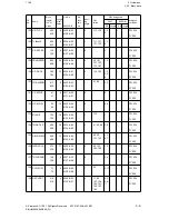
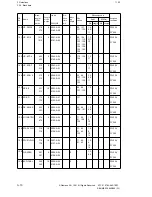
3.3 Explanations of the FB designations
3.3
Explanations of the FB designations
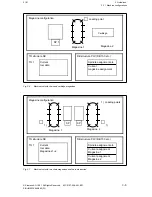
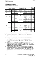
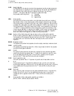
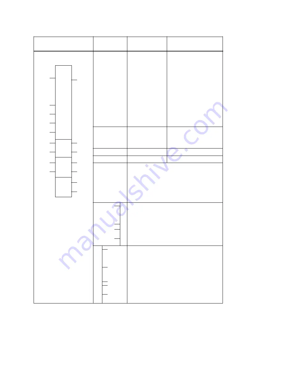
Input signal, static
Input signal acknowledged by the FB
Input signal, positive-going edge evaluated
No DWs permissible as parameters
Input signal which must be applied before calling the FB
Fixed input signal which need not be applied, e.g. NC
signal
FB call
Parameter
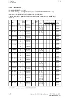
Type of parameter
Allowed
actual operand
I
n.m Input
Q
n.m Output
F
n.m Flag
IB
n
Input byte
QB
n
Output byte
FY
n
Flag byte
DL
n
Data byte left
DR
n
Data byte right
PB
n
I/O byte
IW
n
Input word
QW
n
Output word
FW
n
Flag word
DW
n
Data word
PW
n
I/O word
T
n
No. of timer
DB
n
Data block
FB
n
Function block
PB
n
Program block
SB
n
Sequence block
C
n
No. of counter
BI
Operand with
bit address
BY Operand with
byte address
W
Operand with
word address
Not applicable
Not applicable
Not applicable
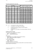
KM
Binary pattern,16 positions
KY
Two absolute values in bytes, from 0 to 255
KH
Hexadecimal number, max. of 4 positions
KS
Two alphanumeric characters
KT
Time value (1.0 to 999.3)
KC
Count value (0 to 999)
KF
Fixed-point number (-32768 to +32767)
I,BI - I
I,BI - Q
I -
Q,BI
Q - Q,BI
Q,...
FB name
§I,..
D,..
B
T
C
$F...
$DW...
*F...
*DW...
$F...
$DW...
*F...
*DW...
- % 1
- %v1
I
Input
Q
Output
B
Block
T
Timer
C
Counter
I,BI
I,BI
-Q
I,BI
- I
§I,..
$...
*...
Q,BI
Q-
Q,BI
I-
Q,BI
$...
*...
% 1
%v1
D
Data
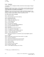
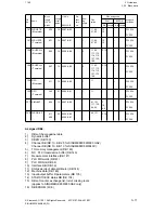
Output signal, static
Output signal which must be acknowledged by the user
Output signal for one cycle (pulse)
Output signal on defined flag or data word which can be
evaluated immediately after the FB
Defined output signal, e.g. NC signal
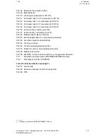
Error number ACCU2 at system stop (STS); ACCU 1
FB number
Additional specification of interface byte number in HIGH-
byte
ACCU 2
3–14
© Siemens AG 1991 All Rights Reserved 6FC5 197-0AA40-1BP1
SINUMERIK 840/880 (PJ)

