Chapter 10 PCI Controller
10-46
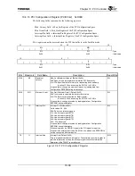
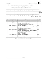
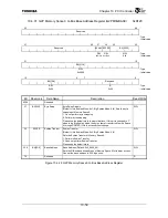
10.4.20 P2G Status Register (P2GSTATUS)
0xD094
31
25 24 23 22 21 20 19 18 17 16
Reserved PMSC
PMEES
PMECLR
M66EN IOBFE IIBFE TOBFE TIBFE
Reserved
R/W1C R/W1C R/W1C
R
R
R
R
R
:
Type
0x0 0x0 0x0 0x0 0x1 0x1 0x1 0x1 :
Initial
value
15
0
Reserved
: Type
:
Initial
value
Bit Mnemonic Field
Name
Description
Read/Write
31:25
Reserved
⎯
24 PMSC
PM State Change
Detected
Power Management State Change (Default: 0x0)
“1” is set to this bit when the PowerState field of the Power Management
Register (PMCSR) is rewritten.
This bit is cleared to “0” when a “1” is written to it. This bit is only valid when
the PCI Controller is in the Satellite mode.
R/W1C
23 PMEES
PME_En Set
Detected
PME_En Set (Default: 0x0)
This bit is set to “1” when the PME_En bit of the PMCSR Register is set to
“1”. When this bit is set, it indicates that the PCI Master (Host) device
enabled PME
*
signal output.
1: Indicates that the PME_En bit is set.
0: Indicates that the PME_En bit is not set.
This bit is cleared to “0” when a “1” is written to it. This bit is only valid when
the PCI Controller is in the Satellite mode.
R/W1C
22 PMECLR
PME
Status
Clear
Detected
PME_Status Clear (Default: 0x0)
This bit indicates that the PME_Status bit of the PMCSR Register was
cleared.
1: Indicates that the PME_Status bit was cleared.
0: Indicates that the PME_Status bit was not cleared.
This bit is cleared to “0” when a “1” is written to it. This bit is only valid when
the PCI Controller is in the Satellite mode.
R/W1C
21 M66EN
66 MHz Drive
Status
M66EN Status (Default: 0x0)
This bit indicates the current status of the M66EN signal. This bit can only
be read. Writes to this bit are invalid.
1: The M66EN signal is asserted.
0: The M66EN signal is deasserted.
R
20 IOBFE
Initiator Out-
Bound FIFO
Empty
Initiator Out-Bound FIFO Empty (Default: 0x1)
1: Indicates that the Initiator Out-Bound FIFO is empty.
0: Indicates that the Initiator Out-Bound FIFO is not empty.
This is a diagnostic function.
R
19 IIBFE
Initiator In-Bound
FIFO Empty
Initiator In-Bound FIFO Empty (Default: 0x1)
1: Indicates that the Initiator In-Bound FIFO is empty.
0: Indicates that the Initiator In-Bound FIFO is not empty.
This is a diagnostic function.
R
18 TOBFE
Target Out-Bound
FIFO Empty
Target Out-Bound FIFO Empty (Default: 0x1)
1: Indicates that the Target Out-Bound FIFO is empty.
0: Indicates that the Target Out-Bound FIFO is not empty.
This is a diagnostic function.
R
17 TIBFE
Target In-Bound
FIFO Empty
Target In-Bound FIFO Empty (Default: 0x1)
1: Indicates that the Target In-Bound FIFO is empty.
0: Indicates that the Target In-Bound FIFO is not empty.
This is a diagnostic function.
R
16:0
Reserved
⎯
Figure 10.4.18 P2G Status Reigster
Summary of Contents for TX49 TMPR4937
Page 1: ...64 Bit TX System RISC TX49 Family TMPR4937 Rev 2 0 ...
Page 4: ......
Page 13: ...Table of Contents ix TMPR4937 Revision History 1 ...
Page 14: ...Table of Contents x ...
Page 15: ...Handling Precautions ...
Page 16: ......
Page 18: ...1 Using Toshiba Semiconductors Safely 1 2 ...
Page 40: ...3 General Safety Precautions and Usage Considerations 3 18 ...
Page 42: ...4 Precautions and Usage Considerations 4 2 ...
Page 43: ...TMPR4937 2005 3 Rev 2 0 ...
Page 44: ......
Page 52: ...Chapter 1 Overview and Features 1 6 ...
Page 156: ...Chapter 7 External Bus Controller 7 56 ...
Page 491: ...Chapter 16 Removed 16 1 16 Removed ...
Page 492: ...Chapter 16 Removed 16 2 ...
Page 493: ...Chapter 17 Removed 17 1 17 Removed ...
Page 494: ...Chapter 17 Removed 17 2 ...
Page 495: ...Chapter 18 Removed 18 1 18 Removed ...
Page 496: ...Chapter 18 Removed 18 2 ...
Page 497: ...Chapter 19 Removed 19 1 19 Removed ...
Page 498: ...Chapter 19 Removed 19 2 ...
Page 506: ...Chapter 20 Extended EJTAG Interface 20 8 ...
Page 530: ...Chapter 22 Pinout and Package Information 22 10 ...
Page 542: ...Chapter 24 Parts Number when Ordering 24 2 ...


