B-35
FX Series PLC User's Manual - Data Communication Edition
N:N Network
7 Creating Programs
7.2 Creating Programs for Master Station (Station No. 0)
A
Comm
on I
te
ms
B
N:
N N
etwo
rk
C
Paral
le
l Li
nk
D
Com
puter Li
nk
E
In
verter
C
omm
uni
cation
F
N
on-Proto
col
C
ommunicati
on
(R
S/RS
2 Instru
ction
)
G
No
n-
Protoc
ol
Co
mmuni
ca
tion
(FX
2N
-2
32IF)
H
Programm
ing
Comm
uni
cation
I
Re
mo
te
Ma
intenance
Apx.A
D
isco
nti
nued
models
7.2
Creating Programs for Master Station (Station No. 0)
Create programs for the master station.
Arbitrarily create programs for reading and writing link devices.
Cautions on setting up the N:N Network
Note the following cautions when creating a program using Structured Ladder, FBD or ST programming in the
FX
1S
, FX
1N
, FX
1NC
, FX
2N
or FX
2NC
PLC.
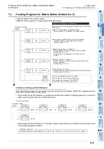
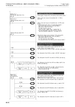
• When setting up the N:N Network in a program using Structured Ladder or FBD programming, connect the
ENO output to the EN input for the MOV instruction.
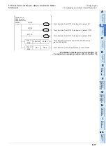
• When setting up the N:N Network in a program using ST programming, use the MOV instruction as shown
in the following program example.
M8038
Parameter setting
FNC 12
MOV
K0
D8176
FNC 12
MOV
K2
D8177
FNC 12
MOV
K1
D8178
FNC 12
MOV
K3
D8179
FNC 12
MOV
K5
D8180
0
Make sure to start the program for setting the N:N Network
from step 0.
Program for setting the N:N Network
Station number setting: 0 (master station)
Station number "0" indicates the master station.
Slave station quantity setting: 2 (2 slave stations)
Set the number of connected slave stations.
[Setting range: 1 to 7]
Refresh range setting: 1 (pattern 1)
Set the pattern of devices used in communication.
[Setting range: 0 to 2]
(Only pattern 0 is applicable in the FX
0N
or FX
1S
Series.)
Number of retries: 3 (3 times)
Set the number of retrying communication after a link
error is detected.
[Setting range: 0 to 10]
Monitoring time: 5 (50 ms)
Set the time by which communication error is determined.
[Setting range: 5 to 255]
Set the communication port to be used.
When using ch1, this step is not required.
When using ch2, program "OUT M8179".
(in the FX
3G
, FX
3GC
, FX
3U
and FX
3UC
)
M8179
Channel
setting
<Program example>
M8038
MOV
EN
ENO
d
D8176
Parameter setting
s
K0
MOV
EN
ENO
d
D8177
s
K2
MOV
EN
ENO
d
D8178
s
K1
MOV
EN
ENO
d
D8179
s
K3
MOV
EN
ENO
d
D8180
s
K5
<Program example>
MOV(MOV(MOV(MOV(MOV(M8038, K0, D8176), K2, D8177), K1, D8178), K3, D8179), K5, D8180);
Summary of Contents for FX-485ADP
Page 2: ......
Page 120: ...B 2 FX Series PLC User s Manual Data Communication Edition N N Network ...
Page 188: ...C 2 FX Series PLC User s Manual Data Communication Edition Parallel Link ...
Page 244: ...D 2 FX Series PLC User s Manual Data Communication Edition Computer Link ...
Page 344: ...E 2 FX Series PLC User s Manual Data Communication Edition Inverter Communication ...
Page 700: ...H 2 FX Series PLC User s Manual Data Communication Edition Programming Communication ...
Page 752: ...I 2 FX Series PLC User s Manual Data Communication Edition Remote Maintenance ...
Page 817: ......

