F-59
FX Series PLC User's Manual - Data Communication Edition
Non-Protocol Communication (RS/RS2 Instruction)
8 Creating Programs (RS2 Instruction)
8.1 Checking Contents of Related Devices
A
Comm
on I
te
ms
B
N:
N N
etwo
rk
C
Paral
le
l Li
nk
D
Com
puter Li
nk
E
In
verter
C
omm
uni
cation
F
N
on-Proto
col
C
ommunicati
on
(R
S/RS
2 Instru
ction
)
G
No
n-
Protoc
ol
Co
mmuni
ca
tion
(FX
2N
-2
32IF)
H
Programm
ing
Comm
uni
cation
I
Re
mo
te
Ma
intenance
Apx.A
D
isco
nti
nued
models
8. Creating Programs (RS2 Instruction)
This chapter explains how to create programs for non-protocol communication using RS2 instruction and how
such programs operate.
The RS2 instruction is dedicated to the FX
3S
, FX
3G
, FX
3GC
, FX
3U
and FX
3UC
PLCs.
RS2 instruction has the following additional functions which are not provided in the RS instruction:
1) Up to 4 characters (bytes) can be specified as the header and terminator.
2) The sum check can be added automatically.
3) The communication port (channel) can be specified.
8.1
Checking Contents of Related Devices
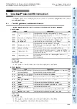
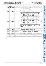
The tables below show devices used in non-protocol communication using RS2 instruction.
Available channels vary depending on the main unit.
For details, refer to Section 3.2.
1. Bit devices
R: Read only
W: Write only
R/W: Read or Write
*1.
FX
3U
, FX
3UC
PLCs Ver. 2.30 or later, and FX
3S
, FX
3G
, FX
3GC
PLCs is applicable.
Device
Name
Description
R/W
ch0
ch1
ch2
M8062
M8063
M8438 Serial communication error
This device turns ON when a communication error occurs.
When this device (serial communication error) turns ON,
D8062, D8063 or D8438 stores the corresponding error
code.
R
M8371
M8401
M8421 Sending wait flag
This device remains ON while the PLC is waiting to send.
R
M8372
M8402
M8422 Sending request
When this device is set to ON, the PLC starts to send.
R/W
M8373
M8403
M8423 Receiving complete flag
This device turns ON when receiving is completed.
While this device (receiving complete flag) is ON, the PLC
cannot receive any receive data.
R/W
—
M8404
M8424 Carrier detection flag
This device turns ON in synchronization with the CD
(DCD) signal.
R
—
M8405
M8425 Data set ready (DSR) flag
*1
This device turns ON in synchronization with the DR (DSR)
signal.
R
M8379
M8409
M8429 Time-out check flag
This device turns ON when data receiving is suspended
and the next set of receive data is not given within the time
set by the time-out time setting device.
R/W
Summary of Contents for FX-485ADP
Page 2: ......
Page 120: ...B 2 FX Series PLC User s Manual Data Communication Edition N N Network ...
Page 188: ...C 2 FX Series PLC User s Manual Data Communication Edition Parallel Link ...
Page 244: ...D 2 FX Series PLC User s Manual Data Communication Edition Computer Link ...
Page 344: ...E 2 FX Series PLC User s Manual Data Communication Edition Inverter Communication ...
Page 700: ...H 2 FX Series PLC User s Manual Data Communication Edition Programming Communication ...
Page 752: ...I 2 FX Series PLC User s Manual Data Communication Edition Remote Maintenance ...
Page 817: ......

