G-20
FX Series PLC User's Manual - Data Communication Edition
Non-Protocol Communication (FX
2N
-232IF)
5 Creating Programs
5.4 Buffer Memory (BFM)
5.4.2
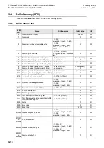
Communication format <BFM #0>
The communication format setting contents are determined when the sending/receiving enable command
(BFM #1, b0) turns ON.
Accordingly, it is necessary to transfer the communication format setting in advance using TO instruction
before setting the sending/receiving enable command to ON.
However, the sending header and sending terminator are determined when the sending command (BFM #1,
b1) turns ON. And the receiving header and receiving terminator are determined when the sending/receiving
enable command (BFM #1, b0) turns ON and the receiving complete flag reset command (BFM #1, b2) turns
ON. Accordingly, if only the header and terminator are changed in the middle of communication, such change
will become valid at the next sending/receiving operation, (so it is not necessary to turn OFF the sending/
receiving enable command).
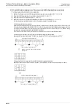
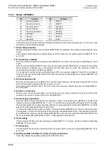
Example of communication format setting (specified in hexadecimal constant)
When specifying the communication format as shown in the table below, use the following program.
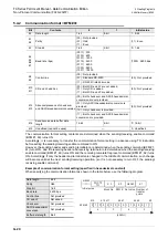
Bit
Contents
0
1
Initial value
b0
Data length
7-bit
8-bit
1 : 8-bit
b1
b2
Parity
(00) : Not provided
(01) : Odd
(11) : Even
(11) : Even
b3
Stop bit
1-bit
2-bit
0 : 1-bit
b4
b5
b6
b7
Baud rate (bps)
(0011) : 300
(0100) : 600
(0101) : 1200
(0110) : 2400
(0111) : 4800
(1000) : 9600
(1001) : 19200
(1000) : 9600 bps
b8
b9
Control line
(00) : Not provided
(00) : Not provided
(01) : Standard RS-232C
(11) : RS-232C interlink mode
b10
b11
CR and LF addition
(00) : Both CR and LF are not added.
(01) : Only CR is added.
(11) : Both CR and LF are added.
(00) : Not provided
b12
b13
Absence/presence of check sum
and ASCII-Hexadecimal conversion
(00) : Both check sum and ASCII-hexadecimal
conversion are not provided.
(00) : Not provided
(01) : Only ASCII-hexadecimal conversion is
provided.
(10) : Only check sum is provided.
(11) : Both check sum and ASCII-hexadecimal
conversion are provided.
b14
Send/receive data buffer data
length
16-bit
8-bit
0 : 16-bit
b15
Undefined (cannot be used)
—
0 : Undefined
Data length
8-bit
Parity
Odd
Stop bit
1-bit
Baud rate
2400 bps
Control line
Not provided
CR and LF
Not added
Check sum
Not provided
ASCII-hexadecimal
conversion
Not provided
Buffer data length
8-bit
M8002
FNC 79
TO
K 0
K 0
H4063
K 1
Block No. BFM # Set value Number of
transfer
points
b15
4
0 1 0 0 0 0 0 0 0 1 1 0 0 0 1 1
b12 b11
b8 b7
b4 b3
b0
0
6
3
(4063H)
BFM #0
Initial pulse
Summary of Contents for FX-485ADP
Page 2: ......
Page 120: ...B 2 FX Series PLC User s Manual Data Communication Edition N N Network ...
Page 188: ...C 2 FX Series PLC User s Manual Data Communication Edition Parallel Link ...
Page 244: ...D 2 FX Series PLC User s Manual Data Communication Edition Computer Link ...
Page 344: ...E 2 FX Series PLC User s Manual Data Communication Edition Inverter Communication ...
Page 700: ...H 2 FX Series PLC User s Manual Data Communication Edition Programming Communication ...
Page 752: ...I 2 FX Series PLC User s Manual Data Communication Edition Remote Maintenance ...
Page 817: ......

