Chapter 5 Instruction Specifications
5-93
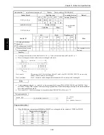
Item number
Application instructions-21
Name
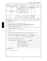
Encode
Ladder format
Condition code
Processing time (
µ
s)
Remark
R7F4
R7F3
R7F2
R7F1
R7F0
Average Maximum
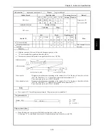
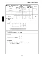
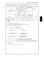
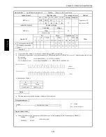
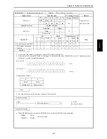
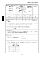
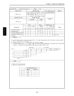
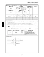
ENCO (d, s, n)
DER
ERR
SD
V
C
↕
z
z
z
↕
Instruction format
Number of steps
Condition
Steps
As per the table
below.
ENCO (d, s, n)
4
Bit
Word
Double word
Usable I/O
X
Y
R,
M
TD, SS,
CU, CT
WX WY
WR,
WM TC DX DY
DR,
DM
C
o
nstant
Other
d
Decode destination head I/O
{
{
s
Word I/O to be encoded
{
n
Number of bits to be
encoded
{
1 to 8 (decimal)
Function
•
Encodes the bit location 2
n
in the range between s and s + 2
n
– 1 where the bit is “1,” and outputs the result to d (n = 1 to 8).
Upper bits (16-n) of d are set to “0.”
•
If n is “0,” the instruction will not be executed and the contents of d retain the original values.
•
If there are more than one bits that are set to “1” between s and s + 2
n
– 1, the upper bit location will be encoded.
•
If all the bits from s to s + 2
n
– 1 are '0', '0' is output to d, and C (R7F0) is equal to '1.' In other cases, C (R7F0) is set to '0.'
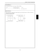
b15
b7
b0
s+2
n
-1
s+B
1
s
2
n
0
0
0
0BH
d
n bits (1 to 8)
Notes
•
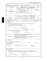
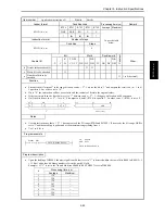
Use this instruction so that s + 2
n
−
1 does not exceed the I/O range (R7BF and M3FFF). If it exceeds the I/O range, DER is
set to '1' and the encoding is performed at the maximum range starting from s.
•
Use 1 to 8 for n.
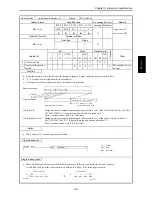
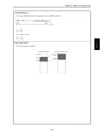
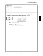
Program example
X00001
LD
X00001
AND DIF1
[
ENCO (WR0000, R000, 4)
]
ENCO (WR0000, R000, 4)
DIF1
Program description
•
Upon the leading of X00001, the most significant bit that is set to “1” is detected within the row of bits R000 to R00F (2
4
–1
= 15 bits), and a four-bit binary number is set in the word I/O of d.
Example) If “1” is set in the 7th and 6th bits of R000 to R00F, H0007 is set in WR0000.
E
NCO (d, s,
n)
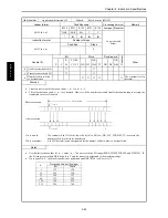
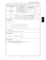
Processing time (
µ
s)
n
Average
Maximum
1
128
–
2
128
–
3
128
–
4
187
–
5
126
–
6
126
–
7
126
–
8
126
–
Summary of Contents for HIDIC MICRO-EH
Page 1: ...HITACHI PROGRAMMABLE CONTROLLER APPLICATION MANUAL NJI 350B X ...
Page 12: ...MEMO ...
Page 14: ...Chapter 1 Features 1 2 MEMO ...
Page 50: ...Chapter 4 Product lineup and wiring 4 18 MEMO ...
Page 196: ...Chapter 5 Instruction Specifications 5 146 ...
Page 263: ...Chapter 11 Communication Specifications 11 10 MEMO ...

