Chapter 5 Instruction Specifications
5-47
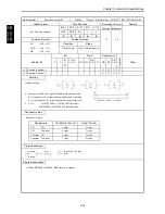
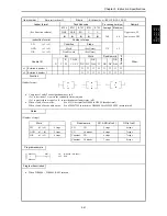
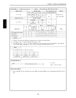
Item number
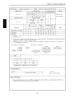
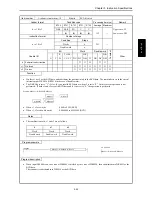
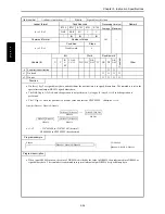
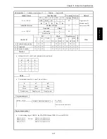
Arithmetic instructions-2
Name
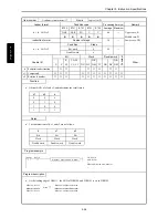
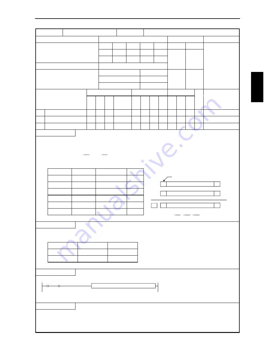
Binary addition (BINARY ADDITION)
Ladder format
Condition code
Processing time (
µ
s)
Remark
R7F4
R7F3
R7F2
R7F1
R7F0
Average
Maximum
d = s1 + s2
DER
ERR
SD
V
C
Upper case: W
z
z
z
↕
↕
45
Lower case: DW
Instruction format
Number of steps
Condition
Steps
d = s1 + s2
Word
4
61
Double word
6
Bit
Word
Double word
Usable I/O
X
Y
R,
M
TD, SS,
CU, CT
WX WY
WR,
WM TC DX DY
DR,
DM
C
onstant
Other
d
Substitution destination
{
{
{
{
{
s1 Augend
{
{
{
{
{
{
{
{
s2 Addend
{
{
{
{
{
{
{
{
Function
•
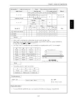
Adds s1 and s2 as the binary data, and substitutes the result into d as the binary data.
•
The C flag is set to “0” if the operation result is within the range of H0000 to HFFFF for word and H00000000 to
HFFFFFFFF for double word. Otherwise, It is set to “1.”
C = s1m
x
s2m + s1m
x
dm + s2m
x
dm
•
The V flag is set to “1” if the operation result is meaningless as signed binary data, and “0” if it is meaningful.
s1
s2
d
V
Positive
Positive
Positive
0
Positive
Positive
Negative
1
Positive
Negative
Positive/Negative
0
Negative
Positive
Negative/Positive
0
Negative
Negative
Positive
1
Negative
Negative
Negative
0
V = s1m
x
s2m
x
dm + s1m
x
s2m
x
dm
Notes
•
The combinations of d, s1 and s2 are as follows:
d
s1
s2
Word
Word
Word
Double word
Double word
Double word
Program example
X00000
DIF0
WR0002 = WR0001
LD
X00000
AND DIF0
[
WR0002 = WR0001
]
Program description
•
The sum of WR0000 and WR0001values is substituted into WR0002 at the leading edge of input X00000.
d =
s1
+
s2
s1
s2
d
0
0
0
s2m
dm
C
+
Most significant bit
s1m
Summary of Contents for HIDIC MICRO-EH
Page 1: ...HITACHI PROGRAMMABLE CONTROLLER APPLICATION MANUAL NJI 350B X ...
Page 12: ...MEMO ...
Page 14: ...Chapter 1 Features 1 2 MEMO ...
Page 50: ...Chapter 4 Product lineup and wiring 4 18 MEMO ...
Page 196: ...Chapter 5 Instruction Specifications 5 146 ...
Page 263: ...Chapter 11 Communication Specifications 11 10 MEMO ...


