Chapter 5 Instruction Specifications
5-19
Item number
Basic instructions-9
Name
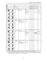
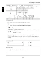
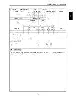
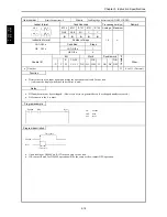
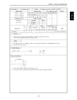
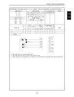
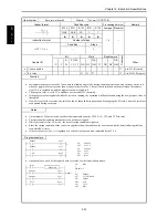
Trailing edge detection (AND DFN, OR DFN)
Ladder format
Condition code
Processing time (
µ
s)
Remark
R7F4
R7F3
R7F2
R7F1
R7F0
Average Maximum
DER
ERR
SD
V
C
DFN n
DFN n
DFN n
DFN n
z
z
z
z
z
Instruction format
Number of steps
1.0
←
AND DFN n
Condition
Steps
OR DFN n
AND DFN n
3
OR DFN n
4
Bit
Word
Double word
Usable I/O
X
Y
R,
M
TD, SS,
CU, CT
WX WY
WR,
WM TC DX DY
DR,
DM
C
onstant
Other
n
Number
{
0 to 511 (Decimal)
Function
•
Detects the fall of an input signal and retains the operation result only for one scan.
( ) indicates the display when the Ladder Editor is used.
Notes
•
DFN number may not be overlapped. (However, no error is generated even if overlapped numbers are used.)
•
DFN cannot use the b contact.
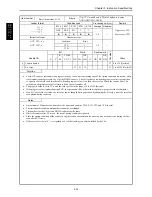
Program example
X00000
R124
LD
AND
OUT
X00000
DFN0
R124
DFN0
Program description
X0
R124
1 scan time
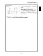
Time chart
•
Upon a fall of X00000, R124 turns on only for one scan.
•
If b-contact is used for X00000, operation will be the same as the a-contact DIF operation.
A
ND DF
N
n
OR
DF
N
n
Summary of Contents for HIDIC MICRO-EH
Page 1: ...HITACHI PROGRAMMABLE CONTROLLER APPLICATION MANUAL NJI 350B X ...
Page 12: ...MEMO ...
Page 14: ...Chapter 1 Features 1 2 MEMO ...
Page 50: ...Chapter 4 Product lineup and wiring 4 18 MEMO ...
Page 196: ...Chapter 5 Instruction Specifications 5 146 ...
Page 263: ...Chapter 11 Communication Specifications 11 10 MEMO ...

