Chapter 5 Instruction Specifications
5-132
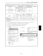
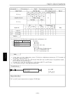
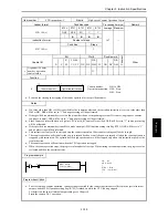
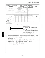
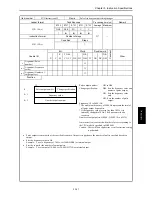
Item number
FUN instructions-8
Name
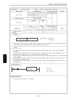
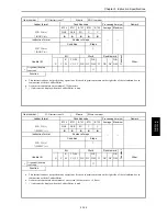
High-speed Counter Current Value Replacement
Ladder format
Condition code
Processing time (
µ
s)
Remark
R7F4
R7F3
R7F2
R7F1
R7F0
Average Maximum
FUN 143 (s)
DER
ERR
SD
V
C
↕
z
z
z
z
Instruction format
Number of steps
175
Condition
Steps
FUN 143 (s)
—
3
Bit
Word
Double word
Usable I/O
X
Y
R,
M
TD, SS,
CU, CT
WX WY
WR,
WM TC DX DY
DR,
DM
C
o
nstant
Other
s
Argument (counter
number)
{
s+1
Argument
(Replacement value
storage area)
{
Function
Counter number: H01 to H04
**:
Disable area
•
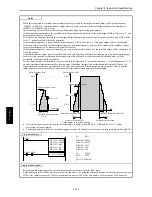
The counter value of the specified counter number will be replaced by the data stored in the replacement value storage area.
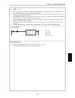
Notes
•
If a value other than H01 to H04 is specified for the counter number, DER will be set to “1” and no processing will be
performed.
•
If the specified counter number is set to a function other than a corresponding external I/O counter (single-phase counter,
two-phase counter), DER will be set to “1”and no processing will be performed.
•
Since Counter 4 is invalid when a 10-point CPU is used, if Counter 4 is specified, DER will be set to “1” and no processing
will be performed.
•
If the specified counter number is unable to make an output (PI/O function setting result by R7F5), DER will be set to “1”
and no processing will be performed.
•
This instruction is only used to rewrite the count value. Other counter settings will not be changed and will not affect the
count operation.
•
If the range for S exceeds the valid range of the I/O, DER will be set to “1” and no processing will be performed.
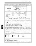
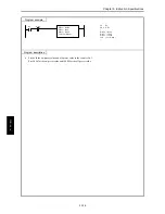
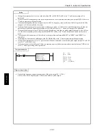
Program example
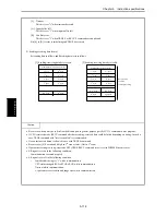
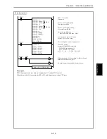
R3
LD
R3
AND DIF3
[
WR30 = H100
WR31 = 1000
FUN 143 (WR30)
]
DIF3
WR30 = H0100
WR31 = 1000
FUN 143 (WR30)
Program description
•
Rewrite the count value of the counter No. 1 to 1000.
S
Counter number
* *
15
8 7
0
S + 1
Replacement value storage area
FUN 143 (s
)
Summary of Contents for HIDIC MICRO-EH
Page 1: ...HITACHI PROGRAMMABLE CONTROLLER APPLICATION MANUAL NJI 350B X ...
Page 12: ...MEMO ...
Page 14: ...Chapter 1 Features 1 2 MEMO ...
Page 50: ...Chapter 4 Product lineup and wiring 4 18 MEMO ...
Page 196: ...Chapter 5 Instruction Specifications 5 146 ...
Page 263: ...Chapter 11 Communication Specifications 11 10 MEMO ...

