


156
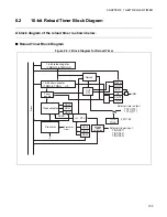
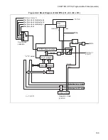
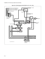
CHAPTER 8 16-BIT RELOAD TIMER
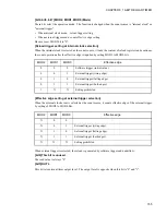
[bit4] RELD
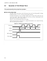
This bit is the reload enable bit. If it is set to "1", reload mode is entered. As soon as the counter value
underflows from "0000
H
" to "FFFF
H
", the contents of the reload register are loaded into the counter and the
count operation is continued.
If this bit is set to "0", one-shot mode is entered and the count operation is stopped when the counter
underflows from "0000
H
" to "FFFF
H
".
TOxE is TO1E and TO2E in the PFR7 (Port Function Register). No output to a pin of the reload timer 0.
[bit3] INTE
This bit is the interrupt request enable bit. If the INTE bit is set to "1", an interrupt request is generated
when the UF bit is set to "1". If it is set to "0", no interrupt request is generated.
[bit2] UF
This bit is the timer interrupt request flag. This bit is set to "1" when the counter value underflows from
"0000
H
" to "FFFF
H
". Write "0" to this bit to clear it.
Writing "1" to this bit is meaningless.
When this bit is read by read-modify-write instructions, "1" is always read.
[bit1] CNTE
This bit is the count enable bit of the timer. Write "1" to this bit to enter the start trigger wait state. Write
"0" to this bit to stop the count operation.
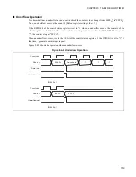
[bit0] TRG
This bit is the software trigger bit. Write "1" to this bit to generate a software trigger, load the contents of
the reload register into the counter, and start the count operation.
Writing "0" to this bit is meaningless. The read value is always "0".
The trigger input to this register is valid only if CNTE=1. No operation occurs if CNTE=0.
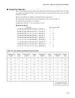
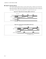
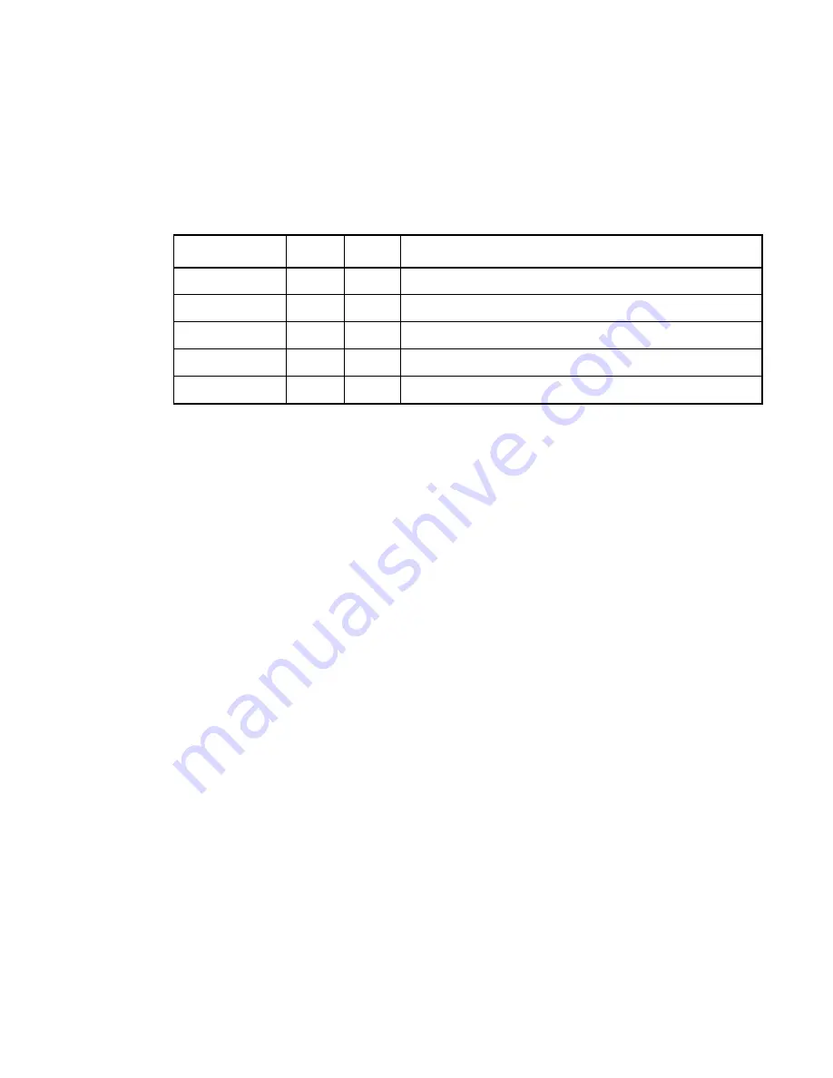
TO1E, TO2E
OUTL
RELD
Output waveform
0
X
X
Output prohibited
1
0
0
"H" rectangular wave while counting
1
1
0
"L" rectangular wave while counting
1
0
1
"L" toggle output when counting starts
1
1
1
"H" toggle output when counting starts
Summary of Contents for FR60Lite
Page 3: ......
Page 5: ......
Page 115: ...100 CHAPTER 3 CPU AND CONTROL UNITS ...
Page 127: ...112 CHAPTER 4 I O PORTS ...
Page 143: ...128 CHAPTER 5 INTERRUPT CONTROLLER ...
Page 155: ...140 CHAPTER 6 EXTERNAL INTERRUPT AND NMI CONTROLLER ...
Page 197: ...182 CHAPTER 9 PPG Programmable Pulse Generator ...
Page 337: ...322 CHAPTER 13 UART ...
Page 417: ...402 CHAPTER 16 DMAC DMA Controller ...
Page 445: ...430 CHAPTER 17 FLASH MEMORY ...
Page 451: ...436 CHAPTER 18 SERIAL PROGRAMMING CONNECTION ...
Page 493: ...478 APPENDIX F Precautions on Handling ...
Page 494: ...479 INDEX INDEX The index follows on the next page This is listed in alphabetic order ...
Page 507: ...492 INDEX ...
Page 509: ......


