


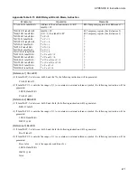


460
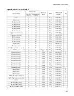
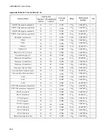
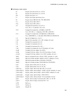
APPENDIX E Instruction Lists
APPENDIX E Instruction Lists
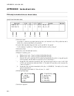
FR family instruction lists are shown below.
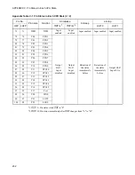
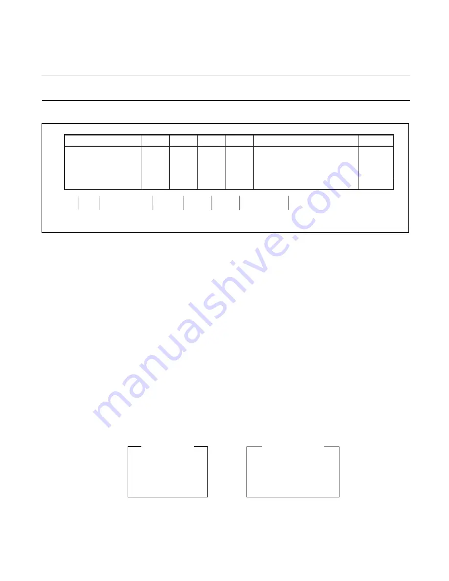
[How to read instruction lists]
(1) Instruction name
An asterisk (*) indicates an extended instruction that is not contained in the CPU specifications and is
obtained by extension or addition by the assembler.
(2) Symbols indicating addressing modes that can be specified for the operand.
For the meaning of symbols, see "Addressing Mode Symbols (on the next page)".
(3) Instruction format
(4) Instruction code in hexadecimal notation
(5) Number of machine cycles
a:
Memory access cycle. It may be extended by the Ready function.
b:
Memory access cycle. It may be extended by the Ready function.
However, the cycle is interlocked if the instruction immediately after refers to a targeted register
for LD operation, and the number of execution cycles is increased by 1.
c:
Interlocked if the instruction immediately after is an instruction that reads or writes to R15, SSP,
or USP, or an instruction in instruction format A. The number of execution cycles is increased by
1 and so it becomes 2.
d:
Interlocked if the instruction immediately after refers to MDH/MDL. The number of execution
cycles is increased to 2.
The minimum cycle number is 1 for each case a, b, c, and d.
(6) Indicating flag changes
(7) Instruction operation
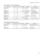
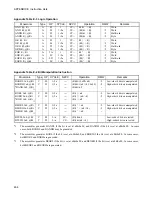
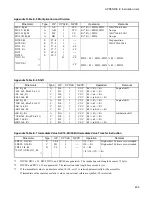
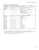
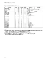
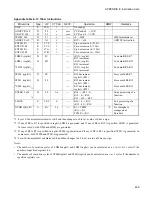
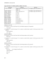
Mnemonic
Type
OP
CYC
NZVC
Operation
Remarks
ADD Rj, Rj
A
AG
1
CCCC
Ri + Rj -> Rj
*ADD #s5, Rj
C
A4
1
CCCC
Ri + s5 -> Ri
(1)
(2)
(3)
(4)
(5)
(6)
(7)
,
,
,
,
,
,
,
,
,
,
,
,
C: Change
N: Negative flag
-: No change
Z: Zero flag
0: Clear
V: Over flag
1: Set
C: Carry flag
Flag meaning
Flag change
Summary of Contents for FR60Lite
Page 3: ......
Page 5: ......
Page 115: ...100 CHAPTER 3 CPU AND CONTROL UNITS ...
Page 127: ...112 CHAPTER 4 I O PORTS ...
Page 143: ...128 CHAPTER 5 INTERRUPT CONTROLLER ...
Page 155: ...140 CHAPTER 6 EXTERNAL INTERRUPT AND NMI CONTROLLER ...
Page 197: ...182 CHAPTER 9 PPG Programmable Pulse Generator ...
Page 337: ...322 CHAPTER 13 UART ...
Page 417: ...402 CHAPTER 16 DMAC DMA Controller ...
Page 445: ...430 CHAPTER 17 FLASH MEMORY ...
Page 451: ...436 CHAPTER 18 SERIAL PROGRAMMING CONNECTION ...
Page 493: ...478 APPENDIX F Precautions on Handling ...
Page 494: ...479 INDEX INDEX The index follows on the next page This is listed in alphabetic order ...
Page 507: ...492 INDEX ...
Page 509: ......


