


49
CHAPTER 3 CPU AND CONTROL UNITS
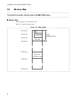
3.8.1
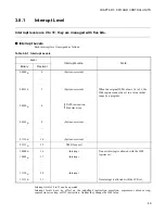
Interrupt Level
Interrupt levels are 0 to 31; they are managed with five bits.
■
Interrupt Levels
Each interrupt level is assigned as follows.
Interrupt levels 16 to 31 can be operated.
Interrupt levels have no effect on the undefined instruction exception, coprocessor absence trap,
coprocessor error trap, or INT instruction. Neither they change the ILM value.
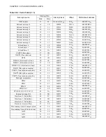
Table 3.8-1 Interrupt Levels
Level
Interrupt source
Note
Binary
Decimal
00000
B
0
(System-reserved)
...
...
...
...
...
...
00011
B
3
(System-reserved) When
the
original ILM value is 16 to 31, the
ILM register cannot be set to a value in that
range by a program.
INTE instruction
Step trace trap
00100
B
4
00101
B
5
(System-reserved)
...
...
...
...
...
...
01110
B
14
(System-reserved)
01111
B
15
NMI (for user)
10000
B
16
Interrupt
No user interrupt is allowed with the ILM
register set.
10001
B
17
Interrupt
...
...
...
...
...
...
11110
B
30
Interrupt
11111
B
31
–
No interrupt is allowed with the ICR set.
{
Summary of Contents for FR60Lite
Page 3: ......
Page 5: ......
Page 115: ...100 CHAPTER 3 CPU AND CONTROL UNITS ...
Page 127: ...112 CHAPTER 4 I O PORTS ...
Page 143: ...128 CHAPTER 5 INTERRUPT CONTROLLER ...
Page 155: ...140 CHAPTER 6 EXTERNAL INTERRUPT AND NMI CONTROLLER ...
Page 197: ...182 CHAPTER 9 PPG Programmable Pulse Generator ...
Page 337: ...322 CHAPTER 13 UART ...
Page 417: ...402 CHAPTER 16 DMAC DMA Controller ...
Page 445: ...430 CHAPTER 17 FLASH MEMORY ...
Page 451: ...436 CHAPTER 18 SERIAL PROGRAMMING CONNECTION ...
Page 493: ...478 APPENDIX F Precautions on Handling ...
Page 494: ...479 INDEX INDEX The index follows on the next page This is listed in alphabetic order ...
Page 507: ...492 INDEX ...
Page 509: ......


