


357
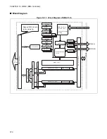
CHAPTER 15 MULTIPLICATION AND ADDITION CALCULATOR
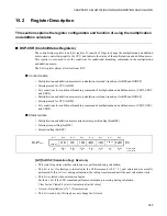
[bit0] GoDSP (calculation start): Write only
RunDSP (Calculation running flag): Read only
•
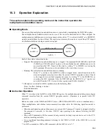
Calculation start is indicated by writing "1" to GoDSP bit. When calculation is stopped (RunDSP = 0),
calculation is activated, and the RunDSP flag is set. If calculation is already ongoing (RunDSP = 1), this
action has no effect.
•
The RunDSP flag indicates that calculation is being executed. This is set by the start of calculation, and
cleared by writing "1" to the HltDSP bit or executing the multiplication and addition macro's HLT
command.
•
When a calculation is being executed (RunDSP = 1), DSP-PC, DSP-LY, X-RAM, Y-RAM, and I-RAM
cannot be accessed from the CPU. Only DSP-CSR and DSP-OT 0 to 7 can be monitored.
•
To start calculation, you must store the start address of the calculation routine in DSP-PC before or at
the same time as activation.
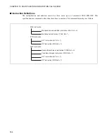
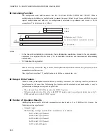
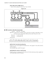
(1) Write-time function (GoDSP: start calculation)
0: No function/No effect on operation
1: When calculation is halted
→
start calculation
If calculation is ongoing
→
has no effect
(2) Read-time function (RunDSP: calculation running flag)
0: Calculation is stopped [initial value]
Clear factor
→
Writing "1" to HltDSP, and executing an HLT command.
1: Calculation is executing.
Set factor
→
start calculation
•
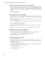
At reset: Be initialized to "0". (Calculation is stopping.)
•
The read / write is possible. Note, however, that as described above, the significance differs depending
on whether reading or writing is being performed.
•
For read-modify-write commands, the value of "0" is always read, regardless of the value of the bit.
■
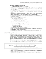
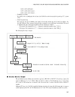
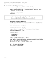
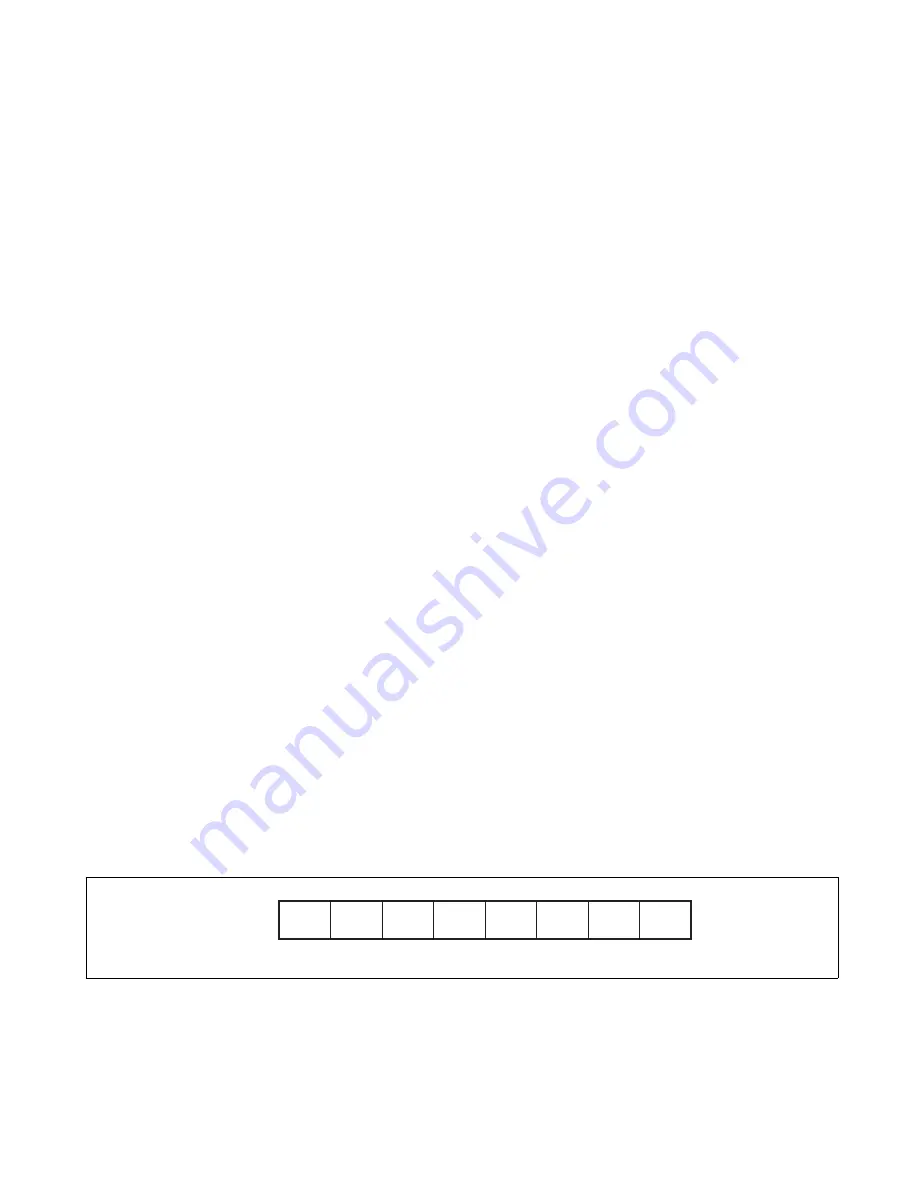
DSP-PC (Program Counter)
The program counter is 8 bits long. It indicates the memory address (I-RAM) where the command code to
be executed by the multiplication and addition macro is stored. Although the program counter is
automatically updated when a command is executed, it can be rewritten via a multiplication and addition
macro JMP. Additionally, access (R/W) from the CPU is only possible when calculation is stopped. You
must store the start address of the calculation routine in DSP-PC before or at the same time as calculations
starts.
After executing the HLT command, or writing "1" to the DSP-CSR HltDSP, DSP-PC points to the address
of the command after the stopped command. Program execution can be continued by again setting GoDSP.
•
At reset: Indeterminate.
•
Although read/write is enabled, access is only possible when multiplication and addition macro
calculation is halted (DSP-CSR: RunDSP = 0).
•
When a calculation is running (DSP-CSR: RunDSP =1), access from the CPU is not possible because it
is separated from the bus.
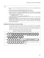
Bit 15
Bit 14
Bit 13
Bit 12
Bit 11
Bit 10
Bit 9
Bit 8
DSP-PC
Address: 0003A0
H
Write
Read
(R/W)
X
(R/W)
X
(R/W)
X
(R/W)
X
(R/W)
X
(R/W)
X
(R/W)
X
(R/W)
X
Read/Write
Initial value
Summary of Contents for FR60Lite
Page 3: ......
Page 5: ......
Page 115: ...100 CHAPTER 3 CPU AND CONTROL UNITS ...
Page 127: ...112 CHAPTER 4 I O PORTS ...
Page 143: ...128 CHAPTER 5 INTERRUPT CONTROLLER ...
Page 155: ...140 CHAPTER 6 EXTERNAL INTERRUPT AND NMI CONTROLLER ...
Page 197: ...182 CHAPTER 9 PPG Programmable Pulse Generator ...
Page 337: ...322 CHAPTER 13 UART ...
Page 417: ...402 CHAPTER 16 DMAC DMA Controller ...
Page 445: ...430 CHAPTER 17 FLASH MEMORY ...
Page 451: ...436 CHAPTER 18 SERIAL PROGRAMMING CONNECTION ...
Page 493: ...478 APPENDIX F Precautions on Handling ...
Page 494: ...479 INDEX INDEX The index follows on the next page This is listed in alphabetic order ...
Page 507: ...492 INDEX ...
Page 509: ......


