


379
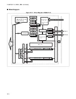
CHAPTER 16 DMAC (DMA Controller)
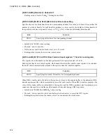
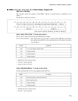
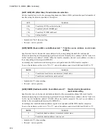
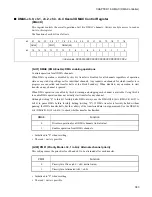
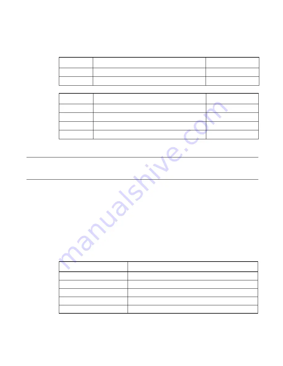
[bit18 to bit16] DSS2 to DSS0 (Dma Stop Status)*: Transfer halt cause indication
This 3-bit code (termination code) indicates the reason why DMA transfer stopped or halted on the
corresponding channel. The termination code meanings are as follows.
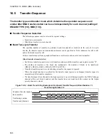
The transfer stop request is only be set when a request from a peripheral circuit is used.
Note:
The "Interrupt generation" column indicates the type of interrupt request that could be generated.
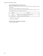
• Initialized to "000B" when resetting.
• Writing "000B" clears the bits.
•
Although both reading and writing are permitted, only "000
B
" is meaningful when writing.
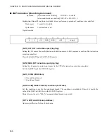
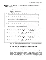
[bit15 to bit8] SASZ7 to SASZ0 (Source Addr count SiZe) *: Count size specification for the
transfer source address
Specifies how much to increment or decrement the transfer source address (DMASA) for the corresponding
channel after each transfer. The value specified by these bits determines by how much the address is
incremented or decremented for each transfer. Whether to increment or decrement the address is specified
by the transfer source address count mode (SADM).
•
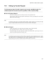
Initialized to "00000000
B
" when resetting.
•
The read / write is possible.
•
If setting other than a fixed address, ensure that the setting matches the transfer data size (WS).
DSS2
Function
Interrupt generation
0
Initial value
None
1
DMA is suspended (DMAH, PAUS bit, interrupt, etc.).
None
DSS1, DSS0
Function
Interrupt generation
00
Initial value
None
01
-
None
10
Transfer halt request
Error
11
Normal completion
End
SASZ
Function
00
H
Address fixed
01
H
Transfer by byte unit
02
H
Transfer by half-word unit
04
H
Transfer by word unit
Other than above
Setting disabled
Summary of Contents for FR60Lite
Page 3: ......
Page 5: ......
Page 115: ...100 CHAPTER 3 CPU AND CONTROL UNITS ...
Page 127: ...112 CHAPTER 4 I O PORTS ...
Page 143: ...128 CHAPTER 5 INTERRUPT CONTROLLER ...
Page 155: ...140 CHAPTER 6 EXTERNAL INTERRUPT AND NMI CONTROLLER ...
Page 197: ...182 CHAPTER 9 PPG Programmable Pulse Generator ...
Page 337: ...322 CHAPTER 13 UART ...
Page 417: ...402 CHAPTER 16 DMAC DMA Controller ...
Page 445: ...430 CHAPTER 17 FLASH MEMORY ...
Page 451: ...436 CHAPTER 18 SERIAL PROGRAMMING CONNECTION ...
Page 493: ...478 APPENDIX F Precautions on Handling ...
Page 494: ...479 INDEX INDEX The index follows on the next page This is listed in alphabetic order ...
Page 507: ...492 INDEX ...
Page 509: ......


