Parameter Description
Parameters
83
(4). Broadcast
The Master will assign the address 0, and the slave will send the message to all the
Slaves. Once receiving a message from the Master, all the Slaves will execute the
requested function without responding to the Master.
2). Communication format
● Basically, the Master will send Query Message to the inverter, which will send the
response message to the Master. The address and function codes are duplicated for
regular communication. Bit 7 of functional code during abnormal communication is
positioned as “1” (=H80). The data bate is set to be the error code.
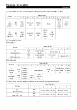
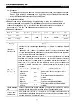
● Message constituents :
Format
Start
①
Address
②
Function
③
Data
④
Error check
Stop
ASCII
H3A
8 bits
8 bits
n×8 bits
2×8 bits
0D 0A
RTU
>=10ms
>=10ms
Message
Content
①
Address
message set
Set range: 0~254.0 is the broadcasting address; 1~254 are the equipment (inverter)
address.
The setup of P.36 is based on the equipment address. The set up is carried out when
the main equipment sends messages to the equipments and when the equipment
sends reply message to the main equipment.
②
Function
message set
Only three functions have been done so far. The equipment carries out actions
according to the request from the equipment. The main equipment sets functional
codes excluded from the table below. The equipment returns error response. It is
determined by the response from the equipment; regular function codes are the
response for regular responses; H80 + function codes are the response for error
responses.
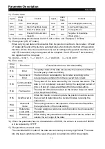
Function name
Function code
Function description
Read multiple
registers
H03
Read slave machine’s continuous register
content.
Write single
register
H06
Write data into slave machine’s single
register.
Function
diagnosis
H08
Function diagnosis
(only for communication calibration)
Write multiple
registers
H10
Write data into slave machine’s multiple
registers.
③
Data message
set
Changes, including the starting address, the number of the write-in or read-out
registers, and the write-in data, are made according to the function codes.
④
Error check
message set
ASCII is the check method for LRC, while RTU is the check method for CRC.(For
more details concerning the verification calculation for LRC and CRC, please refer to
Standard MODBUS Protocol specification.)


