APPENDIX E. COMMUNICATIONS
HF25D LINEAR DC RESISTANCE WELDING CONTROL
990-333
E-11
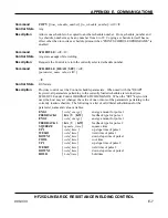
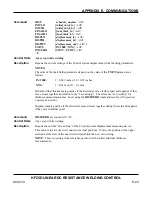
Command
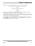
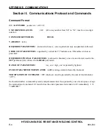
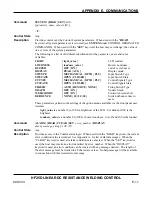
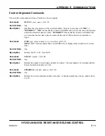
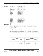
SYSTEM {READ | SET}
<crlf>
[
parameter_name value
<crlf>]
<lf>
Control State
Any
Provides control over the Control's system parameters. When used with the "
READ
"
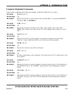
keyword, all system parameters are returned (see
SYSTEM
under CONTROL ORIGINATED
COMMANDS). When used with the "
SET
" keyword, the host may set (change) the value of
one or more of the system parameters.
Description
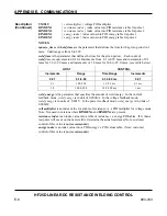
The following is a list of valid literal substitutions for the
parameter_name
and
value
variables:
LIGHT {
light_value
}
LCD contrast
LOUDNESS {
loudness_value
}
Buzzer
Loudness
BUZZER
{ OFF | ON }
end of cycle buzzer
DISPLAY
{ PEAK | AVG }
Display
mode
SWTYPE
{ MECHANICAL | OPTO | PLC}
Input Switch Type
SWSTATE
{ OPEN | CLOSED }
Input Switch State
CTTYPE
{ MECHANICAL | OPTO | PLC}
Control Signals Type
CTSTATE
{ OPEN | CLOSED }
Control Signals State
FIRESW
{ AUTO | REMOTE | NONE }
Firing Switch Type
GRAPH
{ OFF | ON }
Update Graph
WELDABORT
{ OFF | ON }
Footswitch weld abort
DEBOUNCE
{ NONE | 10 | 20 | 30 }
Switch debounce time in
msec
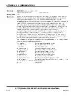
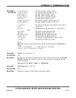
These parameters pertain to the settings of the option menus available via the front panel user
interface.
light_value
is a number 0 to 100 for brightness of the LCD. 0 is dark and 100 is the
brightest.
loudness_value
is a number 0 to 100 for buzzer loudness. 0 is off and 100 is the loudest.
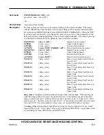
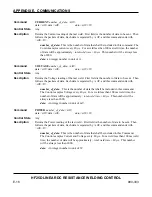
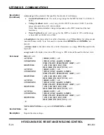
Command
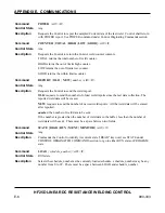
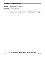
ALARM {READ | CLEAR | SET
error_number
| DISPLAY
alarm_message_string
}
<crlf><lf>
Control State
Any
Description
Provides access to the Control alarm logic. When used with the "READ" keyword, the current
error condition value is returned. See Appendix A. for list of alarm messages. When the
"CLEAR" keyword is used, all alarm conditions are canceled. When the "SET" keyword is
used, the host may invoke an error identified by error_number. When the "DISPLAY"
keyword is used, an error condition can be created with any message desired. The length of
the error message must be limited to 40 characters or less. No help message will be available
in connection with this created error message.
Summary of Contents for HF25A
Page 9: ...HF25D DC RESISTANCE WELDING SYSTEM 990 333 ix ...
Page 10: ......
Page 20: ......
Page 84: ...CHAPTER 6 CALIBRATION HF25D DC RESISTANCE WELDING SYSTEM 990 333 6 4 Final Calibration Setup ...
Page 113: ......
Page 129: ......
Page 153: ......
Page 171: ......


