ISD91200 Series Technical Reference Manual
Release Date: Sep 16, 2019
- 133 -
Revision 2.4
5.4
General Purpose I/O
5.4.1
Overview and Features
Up to 32 General Purpose I/O pins are available on the I91200 series. These are shared peripheral
special function pins under control of the alternate configuration registers. These 32 pins are arranged
in 2 ports named with GPIOA, and GPIOB. Each one of the 32 pins is independent and has
corresponding register bits to control the pin mode function and data.
The I/O type of each GPIO pin can be independently configured as an input, output, open-drain or in a
quasi-bidirectional mode. Upon chip reset, all GPIO pins are configured in quasi-bidirectional mode and
port data register resets high.
When device is in deep power down (DPD) mode, all GPIO pins become high impedance.
GPIO can generate interrupt signals to the core as either level sensitive or edge sensitive inputs. Edge
sensitive inputs can also be de-bounced.
In quasi-bidirectional mode, each GPIO pin has a weak pull-up resistor which is approximately
110K
Ω
~300K
Ω
for V
DD
from 5.0V to 2.4V.
Each pin can generate and interrupt exception to the Cortex M0 core. GPIOB[0] and GPIOB[1] can
generate interrupts to system interrupt number IRQ2 and IRQ3 respectively (see Table 5-21). All other
GPIO generate and exception to interrupt number IRQ4.
5.4.2
GPIO I/O Modes
The I/O mode of each GPIO pin is controlled by the register Px.
(x=A or B).
Each pin has two bits of
control giving four possible states:
5.4.2.1
Input Mode
For Px_MODE
n =
00b the GPIO
x
port [
n
] pin is in Input Mode. The GPIO pin is in a tri-state (high
impedance) condition without output drive capability. The Px_PIN value reflects the status of the
corresponding port pins.
5.4.2.2
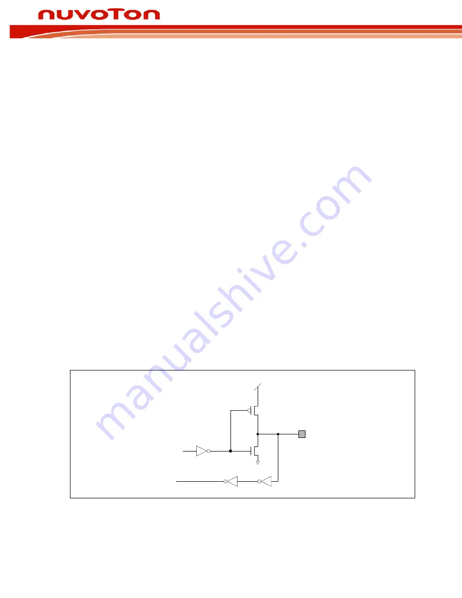
Output Mode
For Px_MODE
n =
01b the GPIO
x
port [
n
] pin is in Output Mode. The GPIO pin supports a digital output
function with current source/sink capability. The bit value in the corresponding bit [n] of P
x_
DOUT is
driven to the pin.
Port Pin[
n
]
PIN[
n
]
DOUT[
n
]
P
N
VDD
Figure 5-6 Output Mode: Push-Pull Output


