ISD91200 Series Technical Reference Manual
Release Date: Sep 16, 2019
- 178 -
Revision 2.4
5.7.8
Capture Timer Operation
Instead of using the PWM generator to output a modulated signal, it can be configured as a capture
timer to measure a modulated input. Capture channel 0 and PWM0CH0 share one timer and Capture
channel 1 and PWM0CH1 share another timer. The capture timer latches PWM-counter to RCAPDAT
when input channel has a rising transition and latches PWM-counter to PWM_FCAPDATx when input
channel has a falling transition. Capture channel 0 interrupt is programmable by setting
PWM_CAPCTL01[1] (Rising latch Interrupt enable) and PWM_CAPCTL01[2] (Falling latch Interrupt
enable) to decide the condition of interrupt occurrence. Capture channel 1 has the same feature by
setting PWM_CAPCTL01[17] and PWM_CAPCTL01[18]. Whenever the Capture module issues a
capture interrupt, the corresponding PWM counter will be reloaded with PERIODx at this moment. Note
that the corresponding GPIO pins must be configured as their alternate function before Capture function
is enabled.
8
7
6
5
4
3
2
1
8
7
6
5
PWM Counter
1
7
Capture Input x
CFLRx
5
CRLRx
Set by H/W
Clear by S/W
CAPIFx
CFL_IEx
CRL_IEx
CAPCHxEN
Set by H/W
Clear by S/W
CFLRIx
Set by H/W
Clear by S/W
Note: X=0~1
CRLRIx
Reload
Reload
(If CNRx = 8)
No reload due to
no CAPIFx
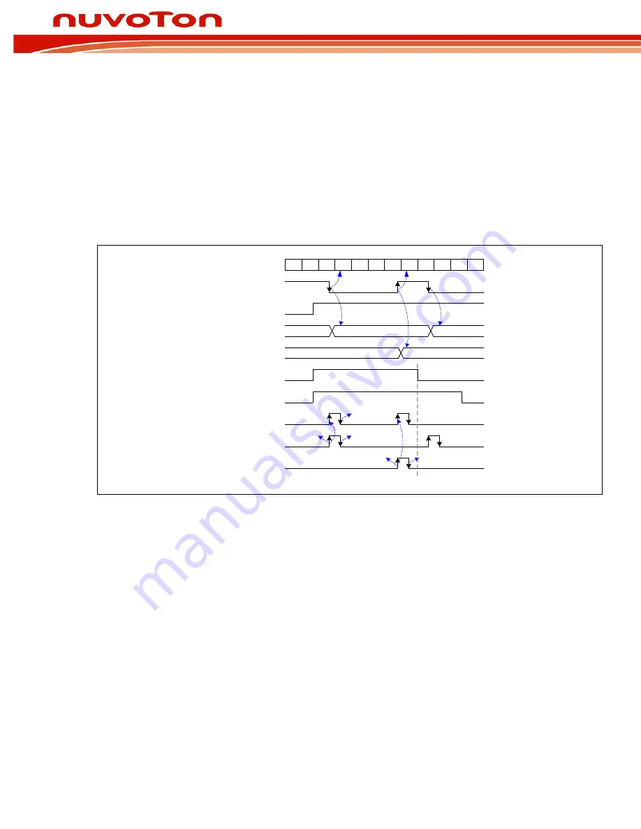
Figure 5-31 Capture Operation Timing
Figure 5-31 Capture Operation Timing demonstrates the case where PERIOD = 8:
1. The PWM counter will be reloaded with PERIODx=8 when a capture interrupt flag (CAPIFx) is
set by a transition on the capture input.
2. The channel low pulse width is given by (PERIOD- RCAPDAT).
3. The channel high pulse width is given by (PERIOD - FCAPDAT).


