ISD91200 Series Technical Reference Manual
Release Date: Sep 16, 2019
- 290 -
Revision 2.4
TX_FIFO
The transmitter is buffered with an 8 byte FIFO to reduce the number of interrupts presented to the
CPU.
RX_FIFO
The receiver is buffered with an 8 byte FIFO (plus three error bits per byte) to reduce the number of
interrupts presented to the CPU.
TX shift Register
Shifts the transmit data out serially
RX shift Register
Shifts the receive data in serially
Modem Control Register
This register controls the interface to the MODEM or data set (or a peripheral device emulating a
MODEM).
Baud Rate Generator
Divides the UART_CLK clock by the divisor to get the desired baud rate clock. Refer to Table 5-116
UART Baud Rate Setting Table for the baud rate equation.
Control and Status Register
This is a register set, including the FIFO control registers (UART_FIFO), FIFO status registers
(UART_FIFOSTS), and line control register (UART_LINE) for transmitter and receiver. The time out
control register (UART_TOUT) identifies the condition of time out interrupt. This register set also
includes the interrupt enable register (UART_INTEN) and interrupt status register (UART_INTSTS) to
enable or disable the responding interrupt and to identify the occurrence of the responding interrupt.
There are six types of interrupts, transmitter FIFO empty interrupt(THERINT), receiver threshold level
reaching interrupt (RDAINT), line status interrupt (overrun error or parity error or framing error or break
interrupt) (RLSINT) , time out interrupt (RXTOINT), MODEM status interrupt (MODEMINT) and Buffer
error interrupt (BUFERRINT).
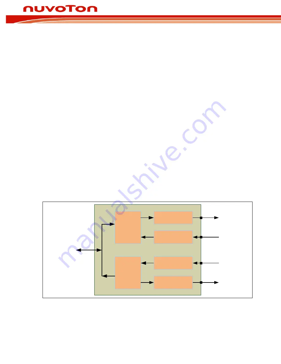
Figure 5-73 Auto Flow Control Block Diagram demonstrates the auto-flow control block diagram.
Tx FIFO
Parallel to Serial
TX
/CTS
Flow Control
Rx FIFO
Serial to Parallel
RX
/RTS
Flow Control
APB
BUS
Figure 5-73 Auto Flow Control Block Diagram


