ISD91200 Series Technical Reference Manual
Release Date: Sep 16, 2019
- 201 -
Revision 2.4
5.8.2
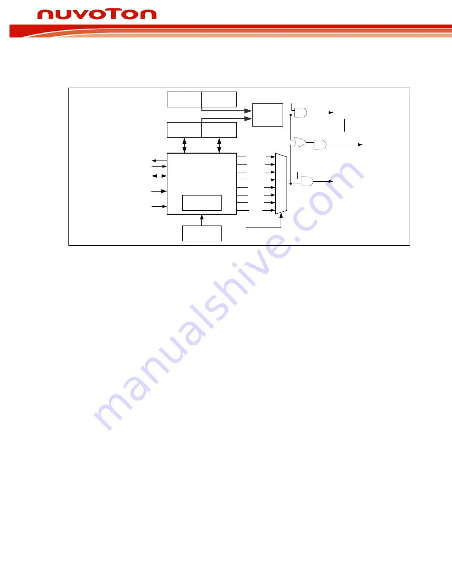
RTC Block Diagram
RTC Time Counter
Control Unit
Time Load
Register (TLR)
Calendar Load
Register (CLR)
Time Alarm
Register (TAR)
Calendar Alarm
Register (CAR)
1/128 change
1/64 change
1/32 change
1/16 change
1/8 change
1/4 change
1/2 change
1 change
(sec)
111
110
101
100
011
010
001
000
RTC_TICK[2:0]
TICKIF(INTSTS[1])
TICKIEN(INTEN[1])
Periodic
Interrupt
Compare
Operation
ALMIEN(INTEN[0])
Alarm
Interrupt
Clock Source
32776 ~32761
Frequency
Compensation
Frequency
Compensation
Register (FCR)
Initiation/Enable
(INIR/AER)
Day of Week
(DWR)
Leap Year Indicator (LIP)
TSSR.24Hr/12Hr
ALMIF(INTSTS[0])
TWKEN(TICK[3])
Wakeup CPU from
Power-down mode
Figure 5-33 RTC Block Diagram
5.8.3
RTC Function Description
5.8.3.1
Access to RTC register
Due to clock frequency difference between RTC clock and system clock, when the user writes new data
to any one of the RTC registers, the register will not be updated until 2 RTC clock periods later (60us).
The programmer should take this into consideration for determining access sequence between
RTC_CLKFMT, RTC_TALM and RTC_TIME.
In addition, the RTC block does not check whether written data is out of bounds for a valid BCD time or
calendar load. RTC does not check validity of RTC_WEEKDAY and RTC_CAL write either.
5.8.3.2
RTC Initiation
When RTC block is powered on, programmer must write 0xA5EB1357 to RTC_INIT register to reset all
logic. RTC_INIT acts as a hardware reset circuit. Once RTC_INIT has been set to0xA5EB1357, internal
reset operation begins. When reset operation is finished, RTC_INIT[0] is set by hardware and RTC is
ready for operation.
5.8.3.3
RTC Read/Write Enable
Register RTC_RWEN[15:0] serves as the RTC read/write password to protect RTC registers.
RTC_RWEN[15:0] have to be set to 0xA965 to enable access. Once set, it will take effect 512 RTC
clocks later (about 15ms). Programmer can read RTC enabled status flag in RTC_RWEN.ENF to check
whether RTC is access enabled. Access is automatically cleared after 200ms.
5.8.3.4
Frequency Compensation
The RTC Frequency Compensation Register (RTC_FREQADJ)allows software to configure digital
compensation to the 32768Hz clock input. The RTC_FREQADJ allows compensation of a clock input in
the range from 32761Hz to 32776Hz. If desired, RTC clock can be measured during manufacture from
a GPIO pin and compensation value calculated and stored in flash memory for retrieval when the
product is first powered on. Following are compensation examples for a higher or lower measured
frequency clock input.


