MDDR Subsystem
Microsemi Proprietary UG0446 User Guide Revision 7.0
11
3.5.2.1
AXI Slave Interface
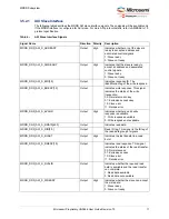
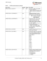
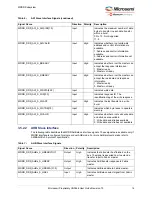
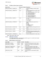
The following table describes the MDDR AXI slave interface signals. These signals will be available only
if the MDDR interface is configured for AXI mode. For more AXI protocol details, refer to AMBA AXI v1.0
protocol specification.
Table 6 •
AXI Slave Interface Signals
Signal Name
Direction Polarity
Description
MDDR_DDR_AXI_S_ARREADY
Output
High
Indicates whether or not the slave is
ready to accept an address and
associated control signals.
1: Slave ready
0: Slave not ready
MDDR_DDR_AXI_S_AWREADY
Output
High
Indicates that the slave is ready to
accept an address and associated
control signals.
1: Slave ready
0: Slave not ready
MDDR_DDR_AXI_S_BID[3:0]
Output
Indicates response ID. The
identification tag of the write response.
MDDR_DDR_AXI_S_BRESP[1:0]
Output
Indicates write response. This signal
indicates the status of the write
transaction.
00: Normal access okay
01: Exclusive access okay
10: Slave error
11: Decode error
MDDR_DDR_AXI_S_BVALID
Output
High
Indicates whether a valid write
response is available.
1: Write response available
0: Write response not available
MDDR_DDR_AXI_S_RDATA[63:0]
Output
Indicates read data.
MDDR_DDR_AXI_S_RID[3:0]
Output
Read ID tag. This signal is the ID tag of
the read data group of signals.
MDDR_DDR_AXI_S_RLAST
Output
High
Indicates the last transfer in a read
burst.
MDDR_DDR_AXI_S_RRESP[1:0]
Output
Indicates read response. This signal
indicates the status of the read transfer.
00: Normal access
01: Exclusive access
10: Slave error
11: Decode error
MDDR_DDR_AXI_S_RVALID
Output
Indicates whether the required read
data is available and the read transfer
can complete.
1: Read data available
0: Read data not available
MDDR_DDR_AXI_S_WREADY
Output
High
Indicates whether the slave can accept
the write data.
1: Slave ready
0: Slave not ready


