MOTOROLA
Chapter 22. SCC BISYNC Mode
22-5
Part IV. Communications Processor Module
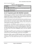
22.5 SCC BISYNC Commands
Transmit and receive commands are issued to the CP command register (CPCR). Transmit
commands are described in Table 22-2.
Receive commands are described in Table 22-2.
Table 22-2. Transmit Commands
Command
Description
STOP
TRANSMIT
After hardware or software is reset and the channel is enabled in the GSMR, the channel is in transmit
enable mode and starts polling the Þrst BD every 64 transmit clocks. This command stops transmission
after a maximum of 64 additional bits without waiting for the end of the buffer and the transmit FIFO to
be ßushed. TBPTR is not advanced, no new BD is accessed, and no new buffers are sent for this
channel. SYNCÐSYNC or DLEÐSYNC pairs are sent continually until a
RESTART
TRANSMIT
is issued. A
STOP
TRANSMIT
can be used when an EOT sequence should be sent and transmission should stop.
After transmission resumes, the EOT sequence should be the Þrst buffer sent to the controller.
Note that the controller remains in transparent or normal mode after it receives a
STOP
TRANSMIT
or
RESTART
TRANSMIT
command.
GRACEFUL
STOP
TRANSMIT
Stops transmission after the current frame Þnishes sending or immediately if there is no frame being
sent. SCCE[GRA] is set once transmission stops. Then BISYNC transmit parameters and TxBDs can
be modiÞed. The TBPTR points to the next TxBD. Transmission resumes when the R bit of the next BD
is set and a
RESTART
TRANSMIT
is issued.
RESTART
TRANSMIT
Lets characters be sent on the transmit channel. The BISYNC controller expects it after a
STOP
TRANSMIT
or a
GRACEFUL
STOP
TRANSMIT
command is issued, after a transmitter error occurs, or after a
STOP
TRANSMIT
is issued and the channel is disabled in its SCCM. The controller resumes transmission
from the current TBPTR in the channelÕs TxBD table.
INIT
TX
PARAMETERS
Initializes all transmit parameters in the serial channelÕs parameter RAM to their reset state. Issue only
when the transmitter is disabled.
INIT
TX
AND
RX
PARAMETERS
resets transmit and receive parameters.
Table 22-3. Receive Commands
Command
Description
RESET
BCS
CALCULATION
Immediately resets the receive BCS accumulator. It can be used to reset the BCS after recognizing a
control character, thus signifying that a new block is beginning.
ENTER
HUNT
MODE
After hardware or software is reset and the channel is enabled in SCCM, the channel is in receive
enable mode and uses the Þrst BD. This command forces the controller to stop receiving and enter
hunt mode, during which the controller continually scans the data stream for an SYN1ÐSYN2
sequence as programmed in the DSR. After receiving the command, the current receive buffer is
closed and the BCS is reset. Message reception continues using the next BD.
CLOSE
RXBD
Used to force the SCC to close the current RxBD if it is in use and to use the next BD for subsequent
data. If data is not being received, no action is taken.
INIT
RX
PARAMETERS
Initializes receive parameters in this serial channelÕs parameter RAM to reset state. Issue only when
the receiver is disabled. An
INIT
TX
AND
RX
PARAMETERS
resets transmit and receive parameters.
Summary of Contents for MPC8260 PowerQUICC II
Page 1: ...MPC8260UM D 4 1999 Rev 0 MPC8260 PowerQUICC II UserÕs Manual ª ª ...
Page 66: ...lxvi MPC8260 PowerQUICC II UserÕs Manual MOTOROLA ...
Page 88: ...1 18 MPC8260 PowerQUICC II UserÕs Manual MOTOROLA Part I Overview ...
Page 120: ...2 32 MPC8260 PowerQUICC II UserÕs Manual MOTOROLA Part I Overview ...
Page 138: ...Part II iv MPC8260 PowerQUICC II UserÕs Manual MOTOROLA Part II Configuration and Reset ...
Page 184: ...4 46 MPC8260 PowerQUICC II UserÕs Manual MOTOROLA Part II ConÞguration and Reset ...
Page 202: ...Part III vi MPC8260 PowerQUICC II UserÕs Manual MOTOROLA Part III The Hardware Interface ...
Page 266: ...8 34 MPC8260 PowerQUICC II UserÕs Manual MOTOROLA Part III The Hardware Interface ...
Page 382: ...10 106 MPC8260 PowerQUICC II UserÕs Manual MOTOROLA Part III The Hardware Interface ...
Page 392: ...11 10 MPC8260 PowerQUICC II UserÕs Manual MOTOROLA Part III The Hardware Interface ...
Page 430: ...Part IV viii MOTOROLA Part IV Communications Processor Module ...
Page 490: ...14 36 MPC8260 PowerQUICC II UserÕs Manual MOTOROLA Part IV Communications Processor Module ...
Page 524: ...17 10 MPC8260 PowerQUICC II UserÕs Manual MOTOROLA Part IV Communications Processor Module ...
Page 556: ...18 32 MPC8260 PowerQUICC II UserÕs Manual MOTOROLA Part IV Communications Processor Module ...
Page 584: ...19 28 MPC8260 PowerQUICC II UserÕs Manual MOTOROLA Part IV Communications Processor Module ...
Page 632: ...21 24 MPC8260 PowerQUICC II UserÕs Manual MOTOROLA Part IV Communications Processor Module ...
Page 652: ...22 20 MPC8260 PowerQUICC II UserÕs Manual MOTOROLA Part IV Communications Processor Module ...
Page 668: ...23 16 MPC8260 PowerQUICC II UserÕs Manual MOTOROLA Part IV Communications Processor Module ...
Page 758: ...27 28 MPC8260 PowerQUICC II UserÕs Manual MOTOROLA Part IV Communications Processor Module ...
Page 780: ...28 22 MPC8260 PowerQUICC II UserÕs Manual MOTOROLA Part IV Communications Processor Module ...
Page 874: ...29 94 MPC8260 PowerQUICC II UserÕs Manual MOTOROLA Part IV Communications Processor Module ...
Page 920: ...31 18 MPC8260 PowerQUICC II UserÕs Manual MOTOROLA Part IV Communications Processor Module ...
Page 980: ...A 4 MPC8260 PowerQUICC II UserÕs Manual MOTOROLA Appendixes ...
Page 1002: ...Index 22 MPC8260 PowerQUICC II UserÕs Manual MOTOROLA INDEX ...
Page 1006: ......


