
MOTOROLA
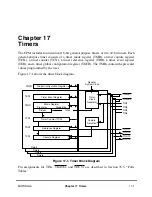
Chapter 17. Timers
17-3
Part IV. Communications Processor Module
output can also be connected internally to the input of another timer, resulting in a 32-bit
timer.
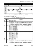
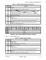
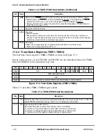
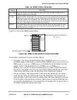
In addition, each timer has a 16-bit TCR used to latch the value of the counter when a
deÞned transition of TIN1, TIN2, TIN3, or TIN4 is sensed by the corresponding input
capture edge detector. The type of transition triggering the capture is selected by the
corresponding TMR[CE] bits. Upon a capture or reference event, the corresponding TER
bit is set and a maskable interrupt request is issued to the interrupt controller. The timers
may be gated/restarted by an external gate signal. There are two gate signalsÑTGATE1
controls timer 1 and/or 2 and TGATE2 controls timer 3 and/or 4. Normal gate mode enables
the count on a falling edge of TGATE
x
and disables the count on the rising edge of
TGATE
x
. This mode allows the timer to count conditionally, based on the state of TGATE
x
.
The restart gate mode performs the same function as normal mode, except it also resets the
counter on the falling edge of TGATE
x
. This mode has applications in pulse interval
measurement and bus monitoring as follows:
¥
Pulse measurementÑThe restart gate mode can measure a low TGATE
x
. The rising
edge of TGATE
x
completes the measurement and if TGATE
x
is connected
externally to TIN
x
, it causes the timer to capture the count value and generate a
rising-edge interrupt.
¥
Bus monitoringÑThe restart gate mode can detect a signal that is abnormally stuck
low. The bus signal should be connected to TGATE
x
. The timer count is reset on the
falling edge of the bus signal and if the bus signal does not go high again within the
number of user-deÞned clocks, an interrupt can be generated.
The gate function is enabled in the TMR; the gate operating mode is selected in the TGCR.
NOTE
TGATE
x
is internally synchronized to the system clock. If
TGATE
x
meets the asynchronous input setup time, the counter
begins counting after one system clock when working with the
internal clock.
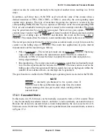
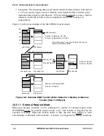
17.2.1 Cascaded Mode
In this mode, two 16-bit timers can be internally cascaded to form a 32-bit counter. Timer
1 may be internally cascaded to timer 2, and timer 3 can be internally cascaded to timer 4.
Because the decision to cascade timers is made independently, the user can select two 16-
bit timers or one 32-bit timer. TGCR is used to put the timers into cascaded mode, as shown
in Figure 17-2.
Summary of Contents for MPC8260 PowerQUICC II
Page 1: ...MPC8260UM D 4 1999 Rev 0 MPC8260 PowerQUICC II UserÕs Manual ª ª ...
Page 66: ...lxvi MPC8260 PowerQUICC II UserÕs Manual MOTOROLA ...
Page 88: ...1 18 MPC8260 PowerQUICC II UserÕs Manual MOTOROLA Part I Overview ...
Page 120: ...2 32 MPC8260 PowerQUICC II UserÕs Manual MOTOROLA Part I Overview ...
Page 138: ...Part II iv MPC8260 PowerQUICC II UserÕs Manual MOTOROLA Part II Configuration and Reset ...
Page 184: ...4 46 MPC8260 PowerQUICC II UserÕs Manual MOTOROLA Part II ConÞguration and Reset ...
Page 202: ...Part III vi MPC8260 PowerQUICC II UserÕs Manual MOTOROLA Part III The Hardware Interface ...
Page 266: ...8 34 MPC8260 PowerQUICC II UserÕs Manual MOTOROLA Part III The Hardware Interface ...
Page 382: ...10 106 MPC8260 PowerQUICC II UserÕs Manual MOTOROLA Part III The Hardware Interface ...
Page 392: ...11 10 MPC8260 PowerQUICC II UserÕs Manual MOTOROLA Part III The Hardware Interface ...
Page 430: ...Part IV viii MOTOROLA Part IV Communications Processor Module ...
Page 490: ...14 36 MPC8260 PowerQUICC II UserÕs Manual MOTOROLA Part IV Communications Processor Module ...
Page 524: ...17 10 MPC8260 PowerQUICC II UserÕs Manual MOTOROLA Part IV Communications Processor Module ...
Page 556: ...18 32 MPC8260 PowerQUICC II UserÕs Manual MOTOROLA Part IV Communications Processor Module ...
Page 584: ...19 28 MPC8260 PowerQUICC II UserÕs Manual MOTOROLA Part IV Communications Processor Module ...
Page 632: ...21 24 MPC8260 PowerQUICC II UserÕs Manual MOTOROLA Part IV Communications Processor Module ...
Page 652: ...22 20 MPC8260 PowerQUICC II UserÕs Manual MOTOROLA Part IV Communications Processor Module ...
Page 668: ...23 16 MPC8260 PowerQUICC II UserÕs Manual MOTOROLA Part IV Communications Processor Module ...
Page 758: ...27 28 MPC8260 PowerQUICC II UserÕs Manual MOTOROLA Part IV Communications Processor Module ...
Page 780: ...28 22 MPC8260 PowerQUICC II UserÕs Manual MOTOROLA Part IV Communications Processor Module ...
Page 874: ...29 94 MPC8260 PowerQUICC II UserÕs Manual MOTOROLA Part IV Communications Processor Module ...
Page 920: ...31 18 MPC8260 PowerQUICC II UserÕs Manual MOTOROLA Part IV Communications Processor Module ...
Page 980: ...A 4 MPC8260 PowerQUICC II UserÕs Manual MOTOROLA Appendixes ...
Page 1002: ...Index 22 MPC8260 PowerQUICC II UserÕs Manual MOTOROLA INDEX ...
Page 1006: ......


